(2) SSB and
CW
modes
The squelch circuit mutes audio output when the
S-meter
signal
is
lower
than
the
[SOL]
control setting
level.
A portion of the 10
MHz
IF signal from the IF amplifier (062
[MainJ.
0101 [Sub])
is
converted into
DC
voltage at the
AGC
detector (044.
065
[Main]. 073. 0104
[Sub))
and
meter amplifier (IC15b [Main]
or
IC23a
[Sub)).
The ampli-
fied
signal
is
applied
to
the
CPU
(DISPLAY unit. IC1) via the
ADMSM
[Main]/ADSSM [Subjline. The
CPU
outputs con-
trol signals
to
the squelch control gate
when
the S-meter
signal
is
low level.
4·1·10
AF
AMPLIFIER CIRCUIT (MAIN UNIT)
The
AF
amplifier circuit amplifies the demodulated signals
to drive a speaker. For the separate speaker function. a
stereo power amplifier
is
used.
AF
signals from the squelch control gate
are
amplified
at
the voltage controlled amplifier
(VCA;
IC30 [Main].
IC31
[Sub]) which functions
as
a volume control using the
[AF]
control signal. The amplified
AF
Signals
are
applied
to
the
AF
power amplifier circuit
(IC32.
pin
2 [Main].
pin
5 [Sub]).
The
amplified audio signals of
SUB
band
are output from
from
pin
7 I
and
are applied
to
the external speaker jack for
the
SUB
band
(J17) via the
[PHONE]
jack (JACK board,
Jl).
When
no
plug
is
connected
to
the jack. the signals are
fed
back
to
the
MAIN
band
audio input (IC32,
pin
2)
and
combined
with
the
MAIN
band
audio. The
mixed
audio
is
applied
to
the internal speaker via the
[PHONE]
jack
and
external speaker jack for the
MAIN
band (J16).
4·1·11 NOISE BLANKER CIRCUIT
(MAIN UNIT)
The
noise blanker circuit detects pulse-type noises,
and
stops IF amplifier operation during detection.
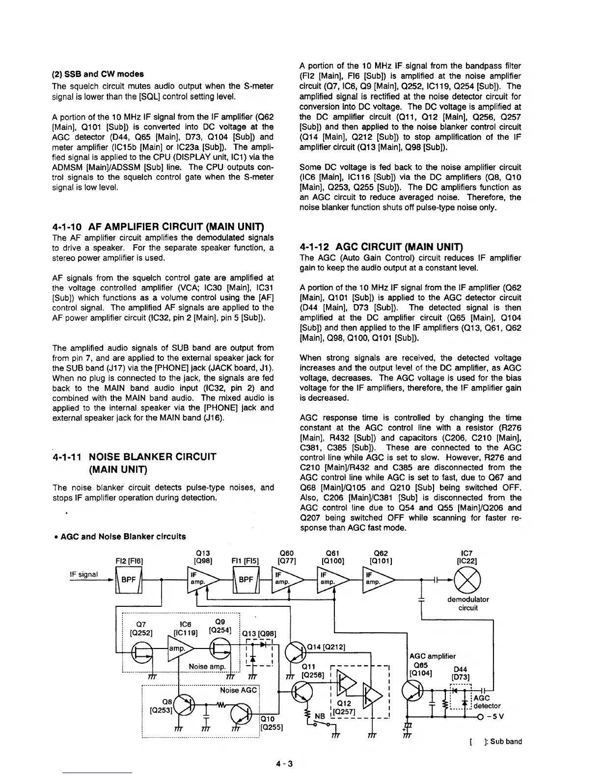
• AGC and Noise Blanker circuits
FI2
[F16)
IF signal
013
(098)
Fl1
[F15)
060
(077)
4-3
A portion of the
10
MHz
IF
signal from the bandpass filter
(F12
[Main], FI6 [Sub])
is
amplified at the noise amplifier
circuit (07.
IC6,
09
[Main], 0252, IC119,
0254
[Sub]). The
amplified signal
is
rectified
at
the noise detector circuit for
conversion
Into
DC
voltage. The
DC
voltage
is
amplified
at
the
DC
amplifier circuit (011,
012
[Main], 0256.
0257
[Sub))
and
then applied to the noise blanker control circuit
(014
[Main].
0212
[Sub]) to
stop
amplification of the IF
amplifier circuit (013
[Main].
098
[Sub)).
Some
DC
voltage
is
fed back to the
nOise
amplifier circuit
(IC6
[Main].
IC116
[Sub))
via the
DC
amplifiers (08,
010
[Main]. 0253, 0255 [Sub]). The
DC
amplifiers function
as
an
AGC
circuit to reduce averaged noise. Therefore. the
noise blanker function shuts off pulse-type noise only.
4-1-12 AGC CIRCUIT (MAIN UNIT)
The
AGC
(Auto
Gain
Control) circuit reduces IF amplifier
gain
to
keep
the audio output
at
a constant level.
A portion of the
10
MHz
IF signal from the IF amplifier (062
[MainJ.
0101
[Sub})
is
applied to the
AGC
detector circuit
(044
[Main].
073
[Sub}).
The detected signal
is
then
amplified
at
the
DC
amplifier circuit (065 [Main]. 0104
[Sub])
and
then
applied
to
the IF amplifiers (013. 061.
062
[Main]. 098, 0100, 0101 [Sub]).
When
strong
signals
are
received, the detected voltage
increases
and
the output level of the
DC
amplifier,
as
AGC
voltage, decreases. The
AGC
voltage
is
used for the bias
voltage for the
IF amplifiers. therefore. the IF amplifier gain
is
decreased.
AGC
response time is controlled by changing the time
constant
at
the
AGC
control line with a resistor (R276
[Main].
R432 [Sub])
and
capacitors
(C206.
C210
[Main).
C381.
C385 [Sub]). These are connected
to
the
AGC
control line
While
AGC
is
set
to
slow.
However, R276
and
C210 [Mainj/R432
and
C385 are disconnected from the
AGC
control line while
AGC
is
set
to
fast. due
to
067
and
068
[Main}/0105
and
0210
[Sub}
being switched OFF.
Also,
C206
[MainJ/C381
[Sub]
is
disconnected from the
AGC
control line due to
054
and
055
[Main]/0206
and
0207
being
switched
OFF
while scanning for faster
re-
sponse
than
AGC
fast
mode
.
061
(0100)
062
IC7
[0101::;»
----4~~®
demodulator
circuit
AGe
amplifier
065
044
[0104]
[073]
.
iAGC
~
.....
J detector
+---------0
-5
V
]:
Sub band