4-3-2 UHF
PLL
CIRCUIT (PLL UNIT)
The UHF PLL circuit generates the 1 st
LO
frequency, and
the
signals are applied to the 1 st mixer circuits
in
the RF-B
unit. The PLL circuit consists of a
VCO, prescaler and DDS
circuits.
The
signal generated at the UHF VCO circuit (05,
D4,
D10)
is
amplified at the buffer-amplifiers
(06,
09),
then applied to
the prescaler circuit
(IC9). The prescaler circuit divides the
applied signal, and outputs it to the UHF DDS circuit (IC6)
via the buffer-amplifier (08).
The pulses output from the UHF DDS circuit are converted
into
DC
voltage at the loop filter circuit (IC7a) and then
applied to the UHF VCO circuit.
The output
DC
voltage from the loop filter circuit is also
applied
to the RF-B unit to control the tuned bandpass filter.
4-4 POWER SUPPLY CIRCUITS
4-4-1
VOLTAGE LINES
Line
Description
HVF
The
voltage from the external power supply
passed through the internal fuse (PA-B unit, F1).
The same
voltage as the HVF line (external
13.8 V
power
supply) which
is
controlled
by
the
[POWER) switch.
Common 9 V converted from the 13.8 V line by
9V
the 9 V regulator circuit (MAIN unit, IC25). The
output
voltage is applied to the PLL,
demodulator and
+5
regulator circuits, etc.
Common 5 V converted from the 13.8 V line by
5V
the 5 V regulator circuit (PLL unit, IC11). The
output
voltage
is
used
in
the PLL unit only.
Common
- 5 V converted from the 13.8 V line
-5V
by the - 5 V DC-DC convertor circuit (MAIN
unit, IC26). The output voltage is applied to the
AGC, APC and ALC circuits, etc.
Common 5 V converted from the 9 V line
by
the
M+5
5 V
regulator circuit (MAIN unit, IC27). The
output
voltage is applied to the BFO circuits and
optional units, etc.
Common 5 V converted from the 13.8 V line
by
F+5
the F+5
regulator circuit (DISPLAY unit, IC13).
The output voltage
is
used
in
the DISPLAY and
SW-A units.
8 V for transmitter circuits which is converted
T8V
from the 9 V line
by
the T8 generator circuit
(MAIN unit, Q36, Q45).
8 V for receiver circuits which is converted from
R8V
the 9 V
lin~
by the
R8
generator circuit (MAIN
unit, Q37, Q41).
9 V for transmitter circuits, particularly the PA-A
PAT9
unit, which is converted from the 9 V
line by the
PAT9 generator circuit
(MAIN unit, Q42, Q45).
9 V for transmitter circuits,
particularly the PA-B
PBT9
unit, which
is
converted from the 9 V line by the
PBT9 generator circuit
(MAIN unit, Q43, Q44).
4-7
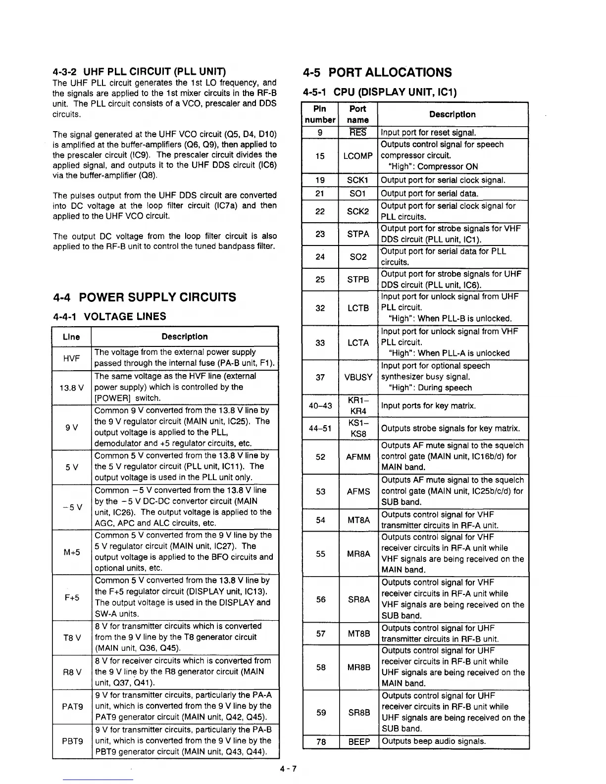
4-5 PORT ALLOCATIONS
4-5-1
CPU (DISPLAY UNIT, IC1)
Pin
Port
Description
number
name
9 RES
Input
port for reset signal.
Outputs control signal
for speech
15
LCOMP
compressor circuit.
"High": Compressor
ON
19
SCK1
Output port for serial clock signal.
21
S01
Output
port for serial data.
22
SCK2
Output
port for serial clock signal for
PLL circuits.
23
STPA
Output
port for strobe signals for VHF
DDS circuit (PLL unit, IC1).
24
S02
"Output port for serial data for PLL
circuits.
25
STPB
Output
port for strobe signals for UHF
DDS circuit (PLL unit, IC6).
Input
port for unlock signal from UHF
32
LCTB
PLL circuit.
"High": When PLL-B is unlocked.
Input
port for unlock signal from VHF
33
LCTA
PLL circuit.
"High": When PLL-A is unlocked
Input
port for optional speech
37
VBUSY
synthesizer busy signal.
"High":
During speech
40-43
KR1-
Input ports for key matrix.
KR4
44-51
KS1-
Outputs strobe signals for key matrix.
KS8
Outputs
AF mute signal to the squelch
52 AFMM
control gate (MAIN unit, IC16b/d) for
MAIN band.
Outputs AF mute signal to the squelch
53
AFMS
control
gate (MAIN unit, IC25b/c/d) for
SUB band.
54
MT8A
Outputs control signal for
VH
F
transmitter circuits
in
RF-A unit.
Outputs control signal for
VH
F
MR8A
receiver circuits
in
RF-A unit while
55
VHF signals are being received
on
the
MAIN band.
Outputs control signal for VHF
SR8A
receiver circuits
in
RF-A unit while
56
VHF signals are being received
on
the
SUB band.
57 MT8B
Outputs control signal for UHF
transmitter circuits
in
RF-B unit.
Outputs control signal for UHF
MR8B
receiver circuits
in
RF-B unit while
58
UHF
signals are being received
on
the
MAIN band.
Outputs control signal for UHF
SR8B
receiver circuits
in
RF-B unit while
59
UHF
signals are being received on the
SUB band.
78 BEEP
Outputs beep audio signals.