4-1-13 S-METER CIRCUIT (MAIN UNIT)
The S-meter circuit indicates the relative received signal
strength
while receiving
and
changes depending
on
the
received signal strength.
(1)
FM
mode
Some of the amplified IF signal
is
applied to the S-meter
detector section
in
the
FM
IF
IC
(lC11
[Main), IC20 [Sub)) to
be
converted into
DC
voltage. The converted signal
is
output from
pin
13
and
applied to the meter amplifier circuit
(IC15a [Main), IC23b [Sub)). The amplified signal
is
then
applied to the
CPU
(DISPLAY unit, IC1) via the ADMSM
[Main)/ADSSM
[Sub)
line. The
CPU
then outputs S-meter
drive signals
as
a METO signal.
(2) sse and
CW
modes
A portion of the
AGC
control signal
is
applied to the S-meter
amplifier. The amplified signal
is
then applied
to
the
CPU
to
drive the S-meter.
4-2 TRANSMITTER CIRCUITS
4-2-1 MICROPHONE AMPLIFIER CIRCUIT
(DISPLAY AND MAIN UNITS)
The microphone amplifier circuit amplifies audio signals
from the microphone or
ACC
connector
and
then applies
them
to
the modulation circuit. One microphone amplifier
circuit
is
commonly used for both FM/SSB
and
VHF/UHF.
Audio
signals from the microphone are amplified at the
variable controlled amplifier (VCA; DISPLAY unit, IC3)
where the amplifier gain
is
controlled with the
[MIG)
control
setting.
The mic
limiter circuit (029) activates when the
[COMP)
switch
is
turned
ON
to limit VCA output. The amplifier gain
is
also controlled with the [COMP
LEVEL)
control
in
such
cases. The amplified audio signals are then applied to the
other microphone amplifier circuit
(IC2a)
in
the
MAIN
unit.
Audio
signals from the
ACC
connector
is
amplified
at
IC2b.
These amplified signals from IC2a or IC2b are applied to
the IDC or the balanced mixer circuit depending
on
oper-
ating mode.
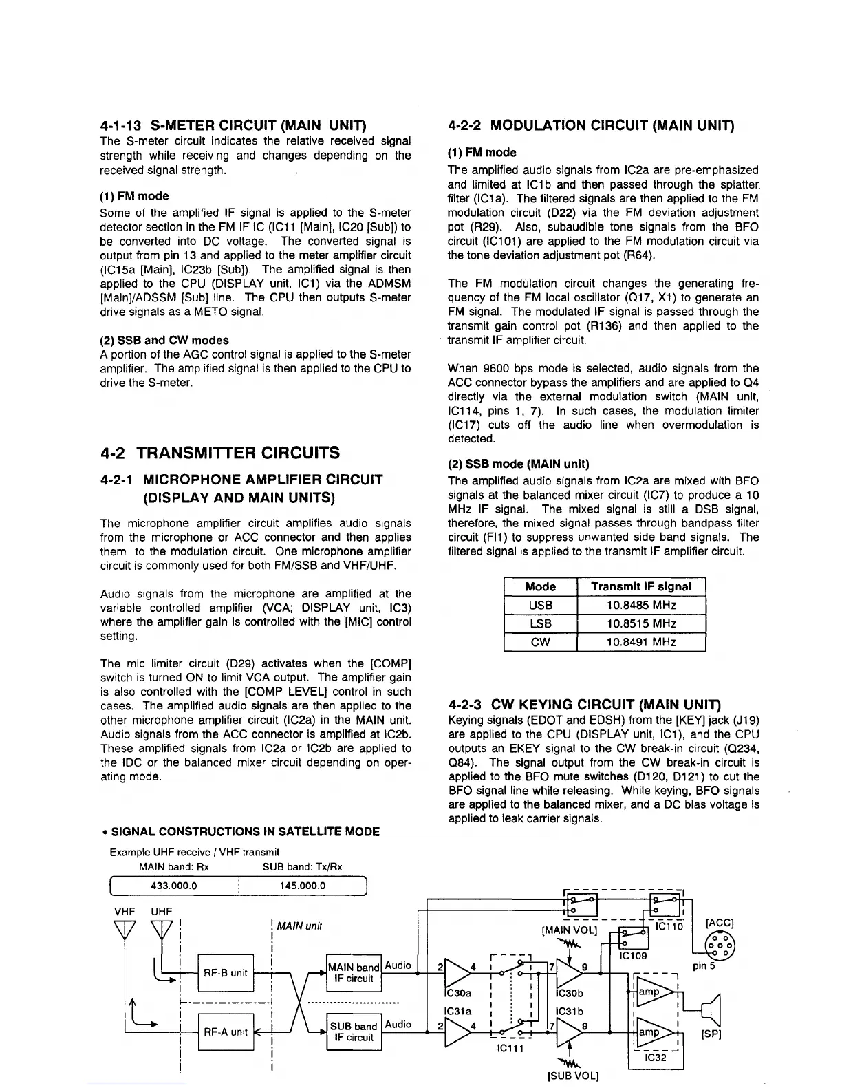
• SIGNAL CONSTRUCTIONS
IN
SATELLITE MODE
Example UHF receive / VHF transmit
MAIN band:
Rx
SUB band: Tx/Rx
433.000.0
VHF UHF
I
I
I
lh~
145.000.0
! MAIN
unit
I
I
RF-B unit
~-t-""'\
I I
L
~.-.-.-.-.-.-.I
I
4-2-2 MODULATION CIRCUIT (MAIN UNIT)
(1)
FM
mode
The amplified audio signals from IC2a are pre-emphasized
and
limited at
IC1
b
and
then passed through the splatter.
filter
(IC1
a).
The filtered signals are then applied to the
FM
modulation circuit (022) via the
FM
deviation adjustment
pot (R29).
Also, subaudible tone signals from the BFO
circuit
(IC1
01) are applied to the
FM
modulation circuit via
the tone deviation adjustment pot (R64).
The
FM
modulation circuit changes the generating fre-
quency of the
FM
local oscillator (017,
X1)
to generate
an
FM
signal. The modulated IF signal
is
passed through the
transmit gain control pot (R136)
and
then applied
to
the
transmit
IF amplifier circuit.
When
9600 bps mode
is
selected, audio signals from the
ACC
connector bypass the amplifiers
and
are applied
to
04
directly via the external modulation switch (MAIN unit,
IC114, pins
1,
7).
In
such cases, the modulation limiter
(IC17)
cuts off the audio line when overmodulation
is
detected.
(2) sse mode (MAIN
unit)
The amplified audio signals from IC2a are mixed with BFO
signals
at
the balanced mixer circuit (IC7) to produce a 10
MHz IF signal. The mixed signal
is
still a
DSB
signal,
therefore, the mixed
signal passes through bandpass filter
circuit
(FI1) to suppress unwanted side band signals. The
filtered signal
is
applied to the transmit IF amplifier circuit.
Mode
Transmit
IF
signal
USB
10.8485
MHz
LSB
10.8515 MHz
CW
10.8491 MHz
4-2-3 CW KEYING CIRCUIT (MAIN UNIT)
Keying signals (EDOT and EDSH) from the
[KEY)
jack (J19)
are applied
to
the
CPU
(DISPLAY unit, IC1),
and
the
CPU
outputs
an
EKEY signal to the
CW
break-in circuit (0234,
084).
The signal output from the
CW
break-in circuit
is
applied to the
BFO
mute switches (0120, 0121) to cut the
BFO
signal line while releasing. While keying, BFO signals
are applied to the balanced mixer,
and
a
DC
bias voltage
is
applied
to
leak carrier signals .
"W....
[SUB VOL)