The output signal from the
CW
break-in circuit
is
also
applied
to
the CW side-tone generator circuit (Q80, Q81).
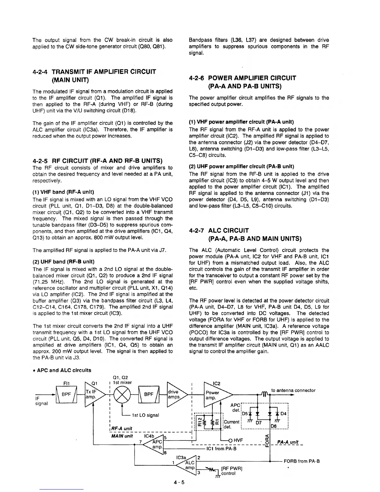
4·2·4 TRANSMIT IF AMPLIFIER CIRCUIT
(MAIN UNIT)
The
modulated
IF
signal from a modulation circuit is applied
to
the IF amplifier circuit (Q1). The amplified IF signal is
then
applied to the RF-A (during VHF) or RF-B (during
UHF) unit via the
V/U
switching circuit (018).
The
gain of the IF amplifier circuit (Q1)
is
controlled by the
ALC
amplifier circuit (IC3a). Therefore, the IF amplifier is
reduced when the output power increases.
4-2-5
RF
CIRCUIT (RF-A AND RF-B UNITS)
The
RF
circuit consists of mixer and drive amplifiers to
obtain the desired frequency
and
level needed
at
a
PA
unit,
respectively.
(1) VHF band
(RF·A unit)
The
IF signal
is
mixed
with
an
LO
signal from the VHF
VCO
circuit (PLL unit,
01,
01-03,
08) at the double-balanced
mixer circuit (01,
02)
to be converted into a VHF transmit
frequency. The mixed signal
is
then passed through the
tunable bandpass filter
(03-05)
to suppress spurious com-
ponents,
and
then amplified at the drive amplifiers (IC1,
Q4,
013)
to obtain
an
approx. 800
mW
output level.
The amplified
RF
signal
is
applied
to
the
PA-A
unit via J7.
(2) UHF band (RF·B
unit)
The IF signal
is
mixed with a 2nd
LO
signal at the double-
balanced
mixer circuit (01,
02)
to produce a 2nd
IF
signal
(71.25
MHz).
The
2nd
LO
signal is generated at the
reference
oscillator
and
multiplier circuit (PLL unit,
X1,
Q14)
via
LO
amplifier (IC2). The 2nd IF signal
is
amplified at the
buffer amplifier (03) via the bandpass filter circuit
(L3,
L4,
C12-C14, C164. C178, C179). The amplified
2nd
IF signal
is applied
to
the 1
st
mixer circuit (IC3).
The 1
st
mixer circuit converts the
2nd
IF signal into a UHF
transmit frequency
with
a 1
st
LO
Signal
from the UHF
VCO
circuit (PLL unit.
as,
04. 010). The converted
RF
signal is
amplified at drive amplifiers (IC1.
04,
aS) to obtain
an
approx. 200
mW
output level. The signal is then applied to
the
PA-B
unit via J3 .
• APC and ALC
circuits
..
I
Bandpass filters (L36,
L37)
are designed between drive
amplifiers to suppress spurious components
in
the RF
signal.
4-2-6 POWER AMPLIFIER CIRCUIT
(PA-A
AND PA·B UNITS)
The power amplifier circuit amplifies the
RF
signals to the
specified output power.
(1) VHF
power
amplifier
circuit
(PA-A
unit)
The
RF
signal from the RF-A unit is applied to the power
amplifier circuit (IC2). The amplified
RF
signal
is
applied to
the antenna connector
(J2)
via the power detector
(04-07,
L8),
antenna switching
(01-03)
and low-pass filter (L3-L5,
C5-C8) circuits.
(2) UHF power amplifier
circuit
(PA·B
unit)
The
RF
signal from the RF-B unit
is
applied to the drive
amplifier circuit
(IC3) to obtain
4-5
W output level and then
applied to the power amplifier circuit (IC1). The amplified
RF
signal
is
applied to the antenna connector
(J1)
via the
power detector
(04,
OS,
L9),
antenna switching
(01-03)
and
low-pass filter (L3-L5, C5-C10) circuits.
4-2-7 ALC CIRCUIT
(PA-A,
PA-B AND MAIN UNITS)
The
ALC
(Automatic
Level
Control) circuit protects the
power module (PA-A unit,
IC2 for VHF and
PA-B
unit.
IC1
for UHF) from a mismatched output load. Also, the
ALC
circuit controls the gain of the transmit IF amplifier
in
order
for the transceiver to output a constant
RF
power set
by
the
[RF PWRl control even when the supplied voltage shifts,
etc.
The
RF
power level is detected at the power detector circuit
(PA-A unit,
04-07,
L8
for
VHF,
PA-B
unit 04.
OS,
L9
for
UHF) to be converted into
OC
voltages. The detected
voltage
(FORA for VHF or FORB for UHF) is applied to the
difference
amplifier (MAIN unit, IC3a). A reference voltage
(POCO)
for IC3a
is
controlled
by
the [RF PWRl control
to
output difference voltages. The output voltage is applied to
the transmit
IF amplifier circuit (MAIN unit, Q1) as
an
AALC
Signal
to control the amplifier gain.
to antenna connector
IF
signal
I
APC~""""
.........•.......
:
I det.
i
i
I
iDS
04:
I
::
I
I'
-
0::-
:Current:
I
'0::
':
OS:
I RF·A unit I
~
......••.•••.
.idet. _
..•••......................
-MAIN-
u-;"ii
-
-'C4b
--
~
- - - - -
-!
<
'--
____
--1~7<
APC
HVF .
~
PA-A unit
!-------------IC1-f~~
PA.S
- - - - - -
-u..
- - - - - - - -
I------------+--
FORB from PA·B
1'----"1'111<::-1
[RF
PWRl
control
4-5