SECTION 2 DISASSEMBLY INSTRUCTIONS
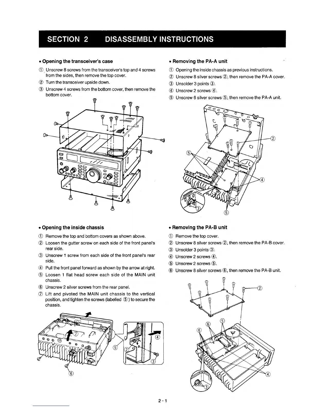
•
Opening
the
transceiver's
case
CD.
Unscrew 8 screws from the transceiver's top and 4 screws
from the sides, then remove the top cover.
® Turn the transceiver upside down.
® Unscrew 4 screws from the bottom cover, then remove the
bottom cover.
•
Opening
the
inside chassis
CD
Remove the top and bottom covers as shown above.
® Loosen the gutter screw on each side of the front panel's
rear side.
® Unscrew t screw from each side of the front panel's rear
side.
® Pull the front panel forward as shown by the arrow at right.
® Loosen 1 flat head
screw
each side
of
the MAIN unit
chassis.
® Unscrew 2 silver screws from the rear panel.
(j) Lift and pivoted the MAIN unit
chassis
to the vertical
position, and tighten the screws (labelled
®)
to secure the
chassis.
2
-1
•
Removing
the
PA-A
unit
CD
Opening the inside chassis as previous instructions.
® Unscrew 8 silver screws ®, then remove the PA-A cover.
® Unsolder 3 points
®.
® Unscrew 2 screws
®.
® Unscrew 6 silver screws
®,
then remove the PA-A unit.
•
Removing
the
PA-B
unit
CD
Remove the top cover.
® Unscrew 8 silver screws
®,
then remove the PA-B cover.
® Unsolder 3 points
®.
® Unscrew 2 screws
®.
® Unscrew 2 screws
®.
® Unscrew 8 silver screws
®,
then remove the PA-B unit.
rv
I