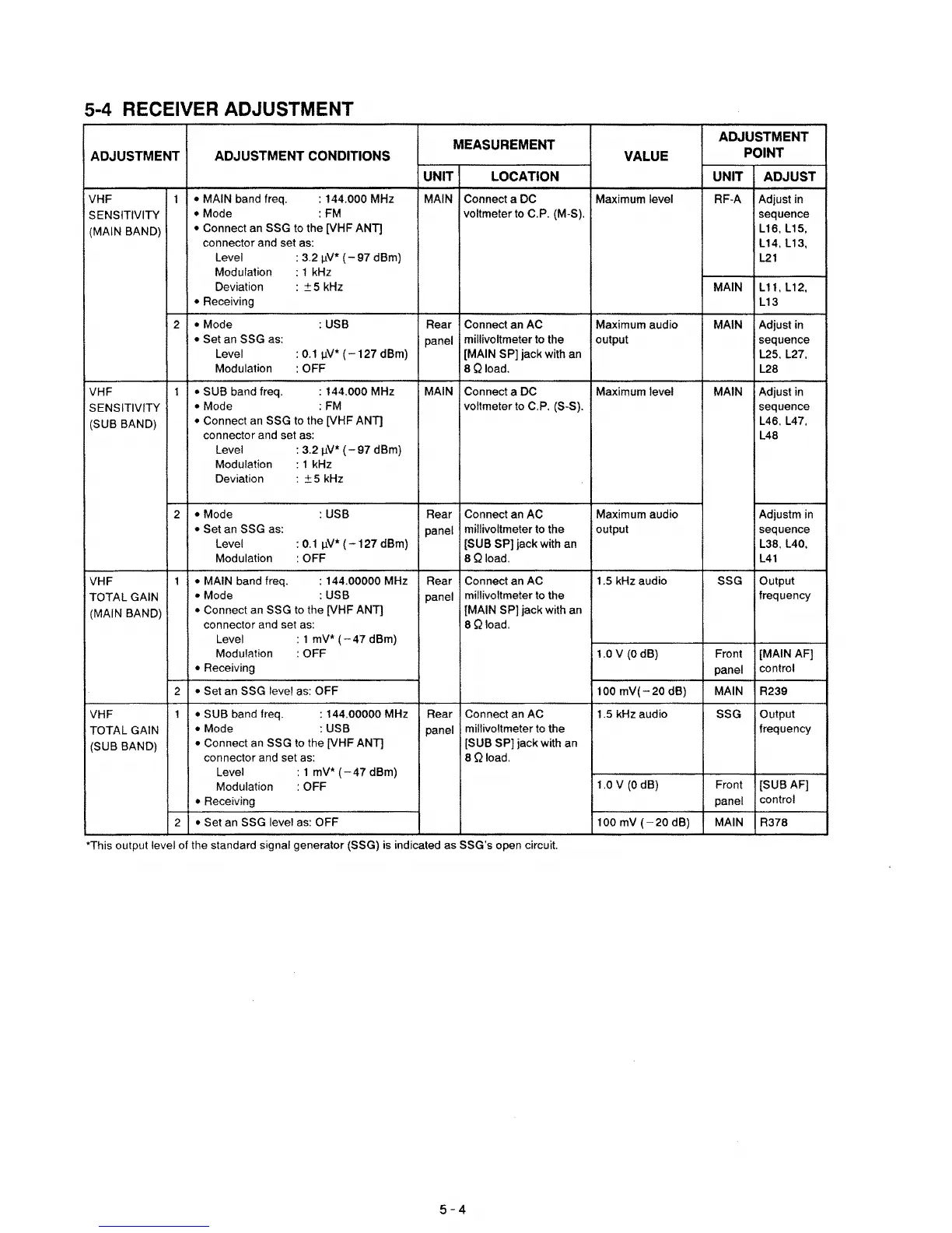
5-4 RECEIVER ADJUSTMENT
MEASUREMENT
ADJUSTMENT
ADJUSTMENT ADJUSTMENT
CONDITIONS VALUE
POINT
UNIT LOCATION UNIT
ADJUST
VHF 1
• MAIN band Ireq.
: 144.000 MHz
MAIN Connect a DC Maximum level RF-A Adjust in
SENSITIVITY
•
Mode
:FM
voltmeter to C.P. (M-S).
sequence
(MAIN BAND)
• Connect
an
SSG to the [VHF ANT]
L16, L15,
connector and set as:
L14, L13,
Level
:
3.2IlV*
(-
97 dBm)
L21
Modulation : 1 kHz
Deviation
:
±5
kHz
MAIN L
11,
L12,
• Receiving
L13
2
• Mode
:USB
Rear Connect an AC Maximum audio
MAIN Adjust in
• Set an SSG as:
panel
millivoltmeter to the
output sequence
Level
:O.lIl
V
*(
127 dBm) [MAIN SP) jack with
an
L25, L27,
Modulation
:
OFF
8Qload.
L28
VHF
1
• SUB band Ireq.
: 144.000 MHz MAIN Connect a DC
Maximum level MAIN Adjust in
SENSITIVITY
•
Mode
:FM
voltmeterto C.P. (S-S). sequence
(SUB BAND)
• Connect
an
SSG to the [VHF ANT]
L46. L47,
connector and set as:
L48
Level :
3.2IlV·
(-97
dBm)
Modulation : 1 kHz
Deviation :
±5
kHz
2
• Mode
:
USB
Rear Connect an AC Maximum audio Adjustm
in
• Set an SSG as:
panel
millivoltmeter to the output sequence
Level
:0.1Il
V
*(-127dBm}
[SUB SP) jack with an L38. L40,
Modulation
:
OFF
8Qload.
L41
VHF
1
• MAIN band Ireq.
: 144.00000 MHz Rear
Connect an
AC
1.5 kHz audio SSG Output
TOTAL GAIN
•
Mode
:USB
panel
millivoltmeter to the frequency
(MAIN BAND)
• Connect
an
SSG to the [VHF ANT]
[MAIN
SP) jack with an
connector and set
as:
8 Qload.
Level
: 1
mV'
(-47
dBm)
Modulation
:
OFF 1.0 V
(0
dB) Front [MAINAF)
• Receiving
panel
control
2
• Set
an
SSG level
as:
OFF
100
mV(-20
dB) MAIN R239
VHF
1
• SUB band Ireq.
: 144.00000 MHz Rear Connect an AC 1.5 kHz audio
SSG
Output
TOTAL
GAIN
• Mode
:USB
panel
millivoltmeter to the frequency
(SUB BAND)
• Connect
an
SSG to the [VHF ANT]
[SUB SP) jack with an
connector and set
as:
8 Qload.
Level : 1 mV*
(-47
dBm)
Modulation :
OFF
1.0
V
(0
dB) Front
[SUBAF]
• Receiving
panel
control
2
• Set
an
SSG level
as:
OFF
100
mV
(-20
dB) MAIN
R378
'This output level
01
the standard signal generator (SSG) is indicated as SSG's open circuit.
5-4