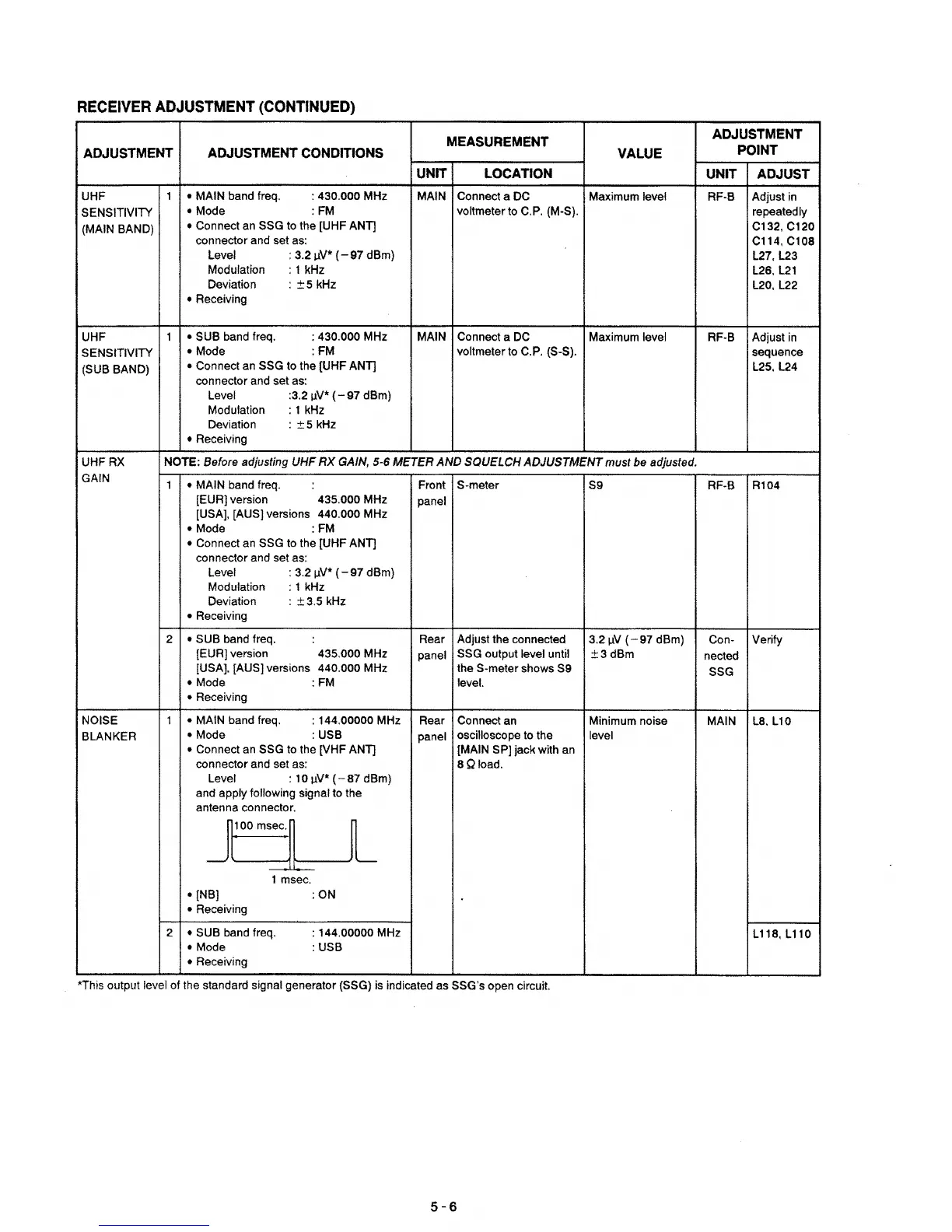
RECEIVER
ADJUSTMENT
(CONTINUED)
MEASUREMENT
ADJUSTMENT
ADJUSTMENT
ADJUSTMENT
CONDITIONS
VALUE
POINT
UNIT LOCATION
UNIT
ADJUST
UHF
1
• MAIN band Ireq.
: 430.000 MHz
MAIN Connect a DC
Maximum level RF-B Adjust in
SENSITIVITY
•
Mode
:FM
voltmeter to C.P. (M-S).
repeatedly
(MAIN BAND)
• Connect
an
SSG
to
the [UHF ANT]
C132,C120
connector and set
as:
C114,Cl08
Level :
3.2IlV*
(-97
dBm)
L27,L23
Modulation
: 1 kHz
L26,
L21
Deviation :
±5
kHz
L20, L22
• Receiving
UHF 1
• SUB band Ireq.
: 430.000 MHz
MAIN Connect a
DC
Maximum level
RF-B Adjust
in
SENSITIVITY
•
Mode
:FM
voltmeter to C.P. (S-S).
sequence
(SUB BAND)
• Connect an SSG to the [UHF ANT] L25, L24
connector and set as:
Level
:3.2
IlV*
(-
97 dBm)
Modulation : 1
kHz
Deviation :
±5
kHz
• Receiving
UHFRX
NOTE: Before adjusting
UHF
RX
GAIN, 5-6 METER
AND
SQUELCH
ADJUSTMENT
must
be adjusted.
GAIN
1
• MAIN band freq.
Front
S-meter
S9
RF-B
Rl04
[EUR] version 435.000 MHz
panel
[USA], [AUS] versions 440.000 MHz
• Mode
:FM
• Connect
an
SSG to the [UHF ANT]
connector and set as:
Level : 3.2
IlV*
(-
97 dBm)
Modulation
: 1 kHz
Deviation :
±3.5
kHz
• Receiving
2
• SUB band freq.
Rear Adjust the connected
3.21lV
(-97
dBm) Con- Verify
[EUR] version
435.000 MHz
panel
SSG output level until
±3dBm
nected
[USA]. [AUS] versions 440.000 MHz the S-meter shows S9
SSG
•
Mode
:FM
level.
•
Receiving
NOISE 1
• MAIN band Ireq.
: 144.00000 MHz
Rear
Connect
an
Minimum noise
MAIN
LS.
L10
BLANKER
• Mode
:USB
panel
oscilloscope to the
level
•
Connect an SSG
to
the [VHF ANT]
[MAIN SP] jack with an
connector and set as:
SQload.
Level : 10
IJ-V*
(-87
dBm)
and apply
following signal to the
antenna connector.
j'0om"l
l
1 msec.
• INB]
:ON
• Receiving
2
• SUB band freq.
:
144.00000 MHz
L
11S.
L 110
•
Mode
:
USB
•
Receiving
*This output
level of the standard signal generator (SSG)
is
indicated as SSG's open circuit.
5-6
 Loading...