Service and Maintenance 5-30
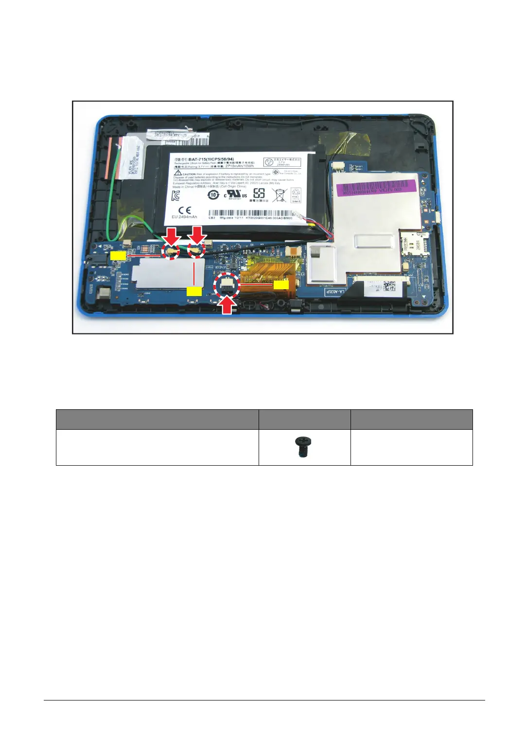
5. Connect the following cable connectors:
• WLAN antenna connector (A)
• GPS antenna connector (B)
• Microphone cable connector (C)
Figure 5-44. Connecting the Cables to the Mainboard
6. Install the lower case (see Lower Case Installation on page 5-14).
Table 5-2. Mainboard Screws
Screw Name Screw Type Quantity
M 1.6 x 3.0 5