16.Furnaceapplicationswithverticalventsrequiringventdi-
ameterincreaserfittingsmusthaveincreaserfittings
installedinverticalportionofthe vent. Condensate will be
trapped in the vent if the vent diameter is increased prior to
having an elbow turned upward. This could cause nuisance
tripping of the pressure switch.
Combustion Air and Vent Piping Insulation
Guidelines
NOTE: Use closed cell, neoprene insulation or equivalent. If Fiber-
glass or equivalent insulation is used it must have a vapor barrier.
Use Rvalues of 7 upto 10', R-11 if exposure exceeds 10'. If Fiber-
glass insulation is used, exterior to the structure, the pipe MUST
be boxed in and sealed against moisture.
1. When the vent or combustion air pipe height above the roof
exceeds 30", or if an exterior vertical riser is used on a hori-
zontal vent to get above snow levels, the exterior portion
MUST be insulated.
2. When combustion air inlet piping is installed above a sus-
pended ceiling, the pipe MUST be insulated with moisture
resistant insulation such as Armaflex or other equivalent
type of insulation.
3. Insulate combustion air inlet piping when run in warm, hu-
mid spaces.
Sizing Combustion Air and Vent Pipe
Consult Table 3 or Table 4 to select the proper diameter exhaust
and combustion air piping. Exhaust and combustion air piping is
sized for each furnace Btuh size based on total lineal vent length
(on inlet oroutlet side), and number of 90 ° elbows required. Two
45 ° elbows can be substituted for one 90 ° elbow. The elbow or el-
bows used for vent termination outside the structure ARE counted,
including elbows needed to bring termination above expected
snow levels. The elbow inside the furnace on the *9MPD IS NOT
included in the count.
Pipe Diameter Table
N9MP1 & *9MPD Models
50,000, 75,000 & 80,000 Btuh Furnaces
40' & (5) 90° elbows with 2" PVC pipe or
70' & (5) 90 ° elbows with 3" PVC pipe
100,000 Btuh Furnace
40' & (5) 90° elbows with 3" PVC pipe or
70' & (5) 90 ° elbows with 3" PVC pipe &
Long Vent Kit (See Tech. Manual)
125,000 Btuh Furnace
40' & (5) 90 ° elbows with 3" PVC pipe
Elbows are DWV Long Radius Type for 2" and 3" vents.
If more than five elbows are required, reduce the length of
both the inlet and exhaust pipes 5' for each additional elbow
used.
NOTE: It is allowable to use larger diameter pipe and fitting than
shown in the tables but not smaller diameters than shown.
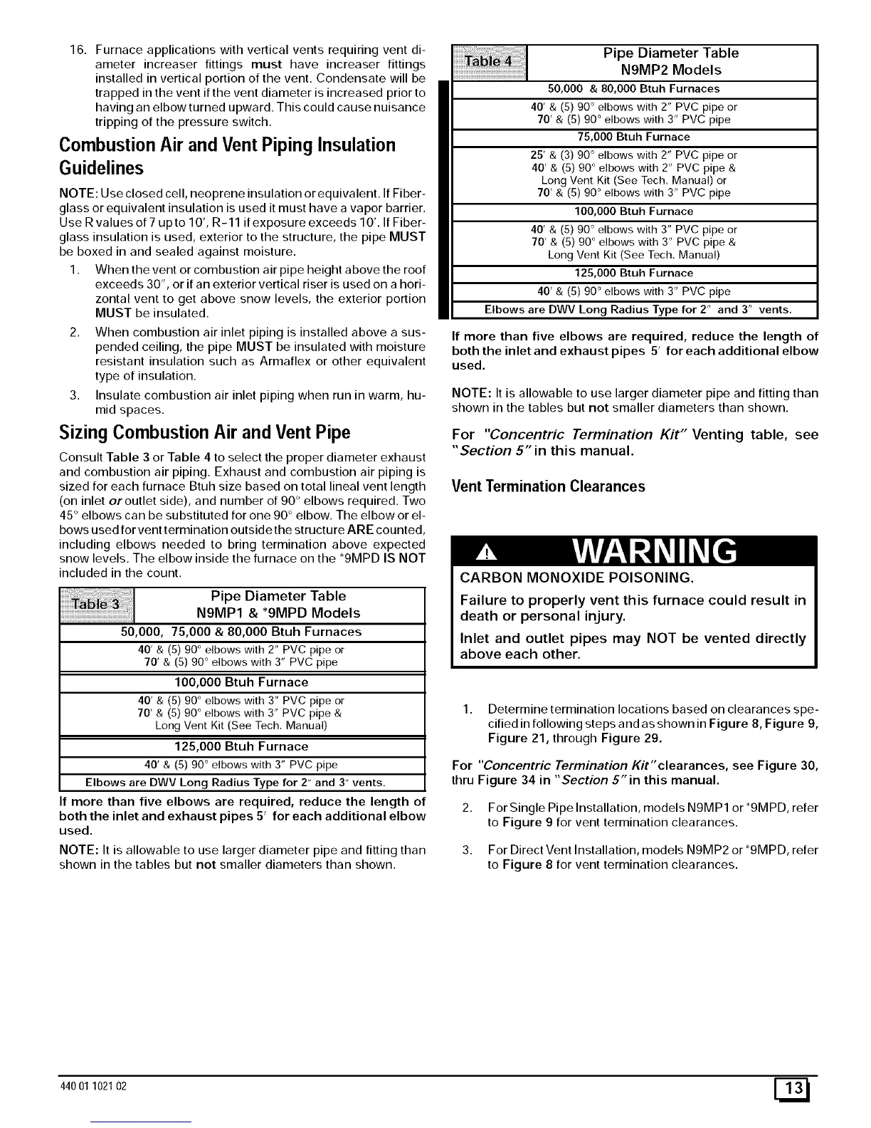
Pipe Diameter Table
N9MP2 Models
50,000 & 80,000 Btuh Furnaces
40' & (5) 90° elbows with 2" PVC pipe or
70' & (5) 90 ° elbows with 3" PVC pipe
75,000 Btuh Furnace
25' & (3) 90° elbows with 2" PVC pipe or
40' & (5) 90 ° elbows with 2" PVC pipe &
Long Vent Kit (See Tech. Manual) or
70' & (5) 90 ° elbows with 3" PVC pipe
100,000 Btuh Furnace
40' & (5) 90° elbows with 3" PVC pipe or
70' & (5) 90 ° elbows with 3" PVC pipe &
Long Vent Kit (See Tech. Manual)
125,000 Btuh Furnace
40' & (5) 90 ° elbows with 3" PVC pipe
Elbows are DWV Long Radius Type for 2" and 3" vents,
If more than five elbows are required, reduce the length of
both the inlet and exhaust pipes 5' for each additional elbow
used.
NOTE: It is allowable to use larger diameter pipe and fitting than
shown in the tables but not smaller diameters than shown.
For "Concentric Termination Kit" Venting table, see
"Section 5" in this manual.
Vent Termination Clearances
CARBON MONOXIDE POISONING.
Failure to properly vent this furnace could result in
death or personal injury.
Inlet and outlet pipes may NOT be vented directly
above each other.
1. Determine termination locations based on clearances spe-
cified in following steps and as shown in Figure 8, Figure 9,
Figure 21, through Figure 29.
For "Concentric Termination Kit"clearances, see Figure 30,
thru Figure 34 in "Section 5"in this manual.
2. For Single Pipe Installation, models N9MP1 or *9MPD, refer
to Figure 9 for vent termination clearances.
3. For Direct Vent Installation, models N9MP2 or*9MPD, refer
to Figure 8 for vent termination clearances.
44001 102102 E_