Subbase for Combustible Floor
NOTE: The three(3) screws in the top panel of the furnace next to
the duct flange MUST be removed to provide serviceability of the
primary heat exchangers in the downflow installation
Note: When using the subbase for combustible floors, the dis-
charge air duct flanges on the furnace MUST be broken down to
provide proper fit up to the subbase. Use duct pliers to bend the
duct flanges flat onto the furnace casing. DO NOT bend the duct
flanges inward (toward the heat exchangers) as air flow restric-
tions may occur.
The Subbase for Combustible Floors MUST be used when a
downflow furnace is set on a combustible floor, even when the fur-
nace is installed on a coil box.
1. CuttheopeningintheflooraccordingtoTable 12. Thehole
in the floor must be cut to the dimensions listed in Table 12
since the base is equipped with locating tabs that center the
base over the opening.
The opening in the base is 11/4 ', shorter and 11/8 ', narrower than
the recommended size of the opening in the floor. This is done to
maintain clearance between the floor and the plenum.
2. Fabricate the plenum to the dimensions given in Table 12.
Note that the dimensions given are outside dimensions.
Subbases for Combustible Floors Dimensions
Subbase for Combustible
Floor Dimensions
Subbase for Combustible
Floors Part Number
Furnace Subbase
NAHH001SB
NAHH002SB
NAHH003SB
NAHH010SB
Subbase for Coil Cabinets
NAHH004SB
NAHH005SB
NAHH006SB
NAHH009SB
Outside Dimension
** Base Spacer Side To Side
3.
4,
5.
H* J* K** L
1511/16 283/4 149/16 16
195/16 283/4 183/16 16
22b/16 283/4 2113/16 16
243/4 283/4 239/16 161/4
1511/16 209/16 149/16 161/4
195/16 209/16 183/16 161/4
23 209/16 2113/16 161/4
2411/16 209/16 239/16 16
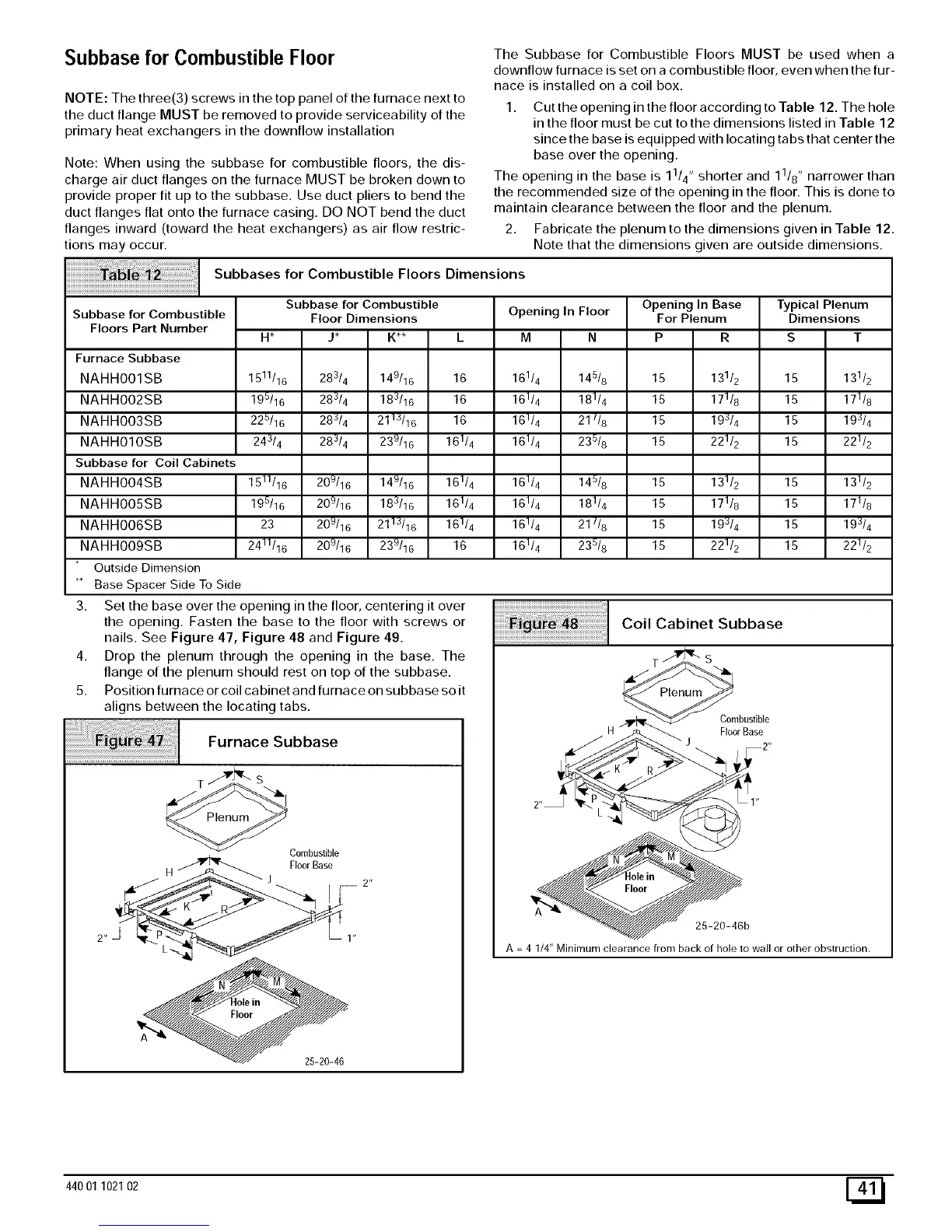
Set the base over the opening in the floor, centering it over
the opening. Fasten the base to the floor with screws or
nails. See Figure 47, Figure 48 and Figure 49.
Drop the plenum through the opening in the base. The
flange of the plenum should rest on top of the subbase.
Position furnace or coil cabinet and furnace on subbase so it
aligns between the locating tabs.
Furnace Subbase
T S
Opening In Floor
161/4
161/4
161/4
161/4
145/8
181/4
21//8
235/8
145/8
181/4
21//8
235/8
Opening In Base
For Plenum
15
15
15
15
131/2
171/8
193/4
221/2
131/2
171/8
193/4
221/2
Typical Plenum
Dimensions
S T
15
15
15
15
15
15
15
15
15
15
15
15
Coil Cabinet Subbase
161/4
161/4
161/4
161/4
25-20-46
T _ S\,IL
Combustible
H FloorBase
J
131/2
171/8
19_/4
221/2
131/2
17118
193/4
221/2
25-20-46b
A 4 1/4" Minimum clearance from back of hole to wall or other obstruction.
44001 102102 [_