............................=;;;;;;;;;;;;;===== ; ==========_i_!ii ii !1 Upflow Installations Top vent
On Some Models
ONLY
Single Pressure Switch
VentDrain
& Clamps
(Optional)
Dual Pressure Switch Detail
Drain Tube
Black Rubber
l/z" ID & Clamps
Drain Tube
Corrugate(
& Clamps
Drain Connector Black PVC
3/4" PVC X 1/2" CPVC
(Loose parts bag)
Casing Grommet
S/8"ID
(Looseparts bag)
Relief Tube
Black Rubber
3/16" ID
Street Elbow
1/2" CPVC
(Loose parts bag)
Drain Line Vent Tee 3/4" PVC or
1/2" CPVC (Field supplied)
DrainTube BlackRubber /8 ID& Clamps,
Cut lengthto fit (Loosepartsbag)
25-24-80
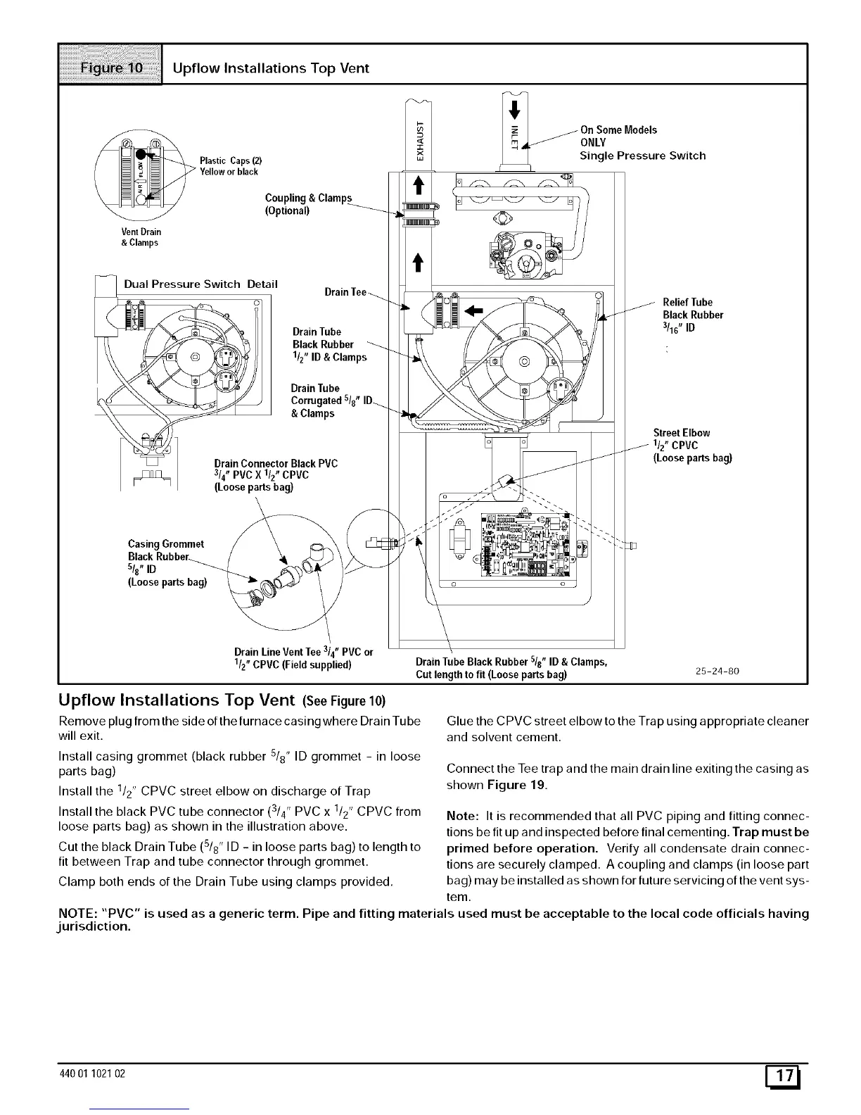
Upflow Installations Top Vent (SeeFigure10)
Remove plug from the side of the furnace casing where Drain Tu be
will exit.
Install casing grommet (black rubber 5/8" ID grommet - in loose
parts bag)
Install the 1/2" CPVC street elbow on discharge of Trap
Install the black PVC tube connector (3/4" PVC x 1/2" CPVC from
loose parts bag) as shown in the illustration above.
Cut the black Drain Tube (5/8" ID - in loose parts bag) to length to
fit between Trap and tube connector through grommet.
Clamp both ends of the Drain Tube using clamps provided.
Glue the CPVC street elbow to the Trap using appropriate cleaner
and solvent cement.
Connect the Tee trap and the main drain line exiting the casing as
shown Figure 19.
Note: It is recommended that all PVC piping and fitting connec-
tions be fit up and inspected before final cementing. Trap must be
primed before operation. Verify all condensate drain connec-
tions are securely clamped. A coupling and clamps (in loose part
bag) may be installed as shown for future servicing of the vent sys-
tem.
NOTE: "PVC" is used as a generic term. Pipe and fitting materials used must be acceptable to the local code officials having
jurisdiction.
44001 102102 E_