bustionorthefurnacecanuseairfrominsidethestructureforcom-
bustion.TheINLETairpipeisoptional.Ifcombustionaircomes
frominsidethestructure,adequatemakeupairMUSTbeprovided
tocompensateforoxygenburned.SeeConfined Space Installa-
tion in the Combustion and Ventilation Air chapter. If combus-
tion air is drawn from outside the structure, it MUST be taken from
the same atmospheric pressure zone as the vent pipe.
Contaminated Combustion Air
Installations in certain areas or types of structures will increase the
exposure to chemicals or halogens that may harm the furnace.
The following areas or types of structures may contain or have ex-
posure to the substances listed below. The installation must be
evaluated carefully as it may be necessary to provide outside air
for combustion.
• Commercial buildings.
• Buildings with indoor pools.
• Furnaces installed in laundry rooms.
• Furnaces installed in hobby or craft rooms.
• Furnaces installed near chemical storage areas.
• Permanent wave solutions for hair.
• Chlorinated waxes and cleaners.
• Chlorine based swimming pool chemicals.
• Water softening chemicals.
• De-icing salts or chemicals.
• Carbon tetrachloride.
• Halogen type refrigerants.
• Cleaning solvents (such as perchloroethylene).
• Printing inks, paint removers, varnishes, etc.
• Hydrochloric acid.
• Sulfuric Acid.
• Solvent cements and glues.
• Antistatic fabric softeners for clothes dryers.
• Masonry acid washing materials.
Vent and Combustion Air Piping Guidelines
3) ABS to PVC transition joints REQUIRE a special sol-
vent cement that meets the requirements of ASTM D3138.
4) Refer to ASTM D2855 for general procedure to use for
cementing plastic pipe and fittings.
NOTE: In order to create a seal that allows future removal of pipe,
RTV sealant MUST be used on the inlet pipe where it joins to the
furnace.
NOTE: All vent piping MUST be installed in compliance with local
codes or ordinances, these instructions, good trade practices, and
codes of country having jurisdiction.
1. Determine the best routing and termination for the vent pipe
and air inlet pipe by referring to all of the instructions and
guidelines in this Section.
2. Determine the size required for the vent pipe and air inlet
pipe.
3. Loosely assemble all venting parts without adhesive (pipe
joint cement) for correct fit before final assembly.
4. Furnace shall be installed so as to prevent the accumulation
of condensate.
5. Use of vertical piping is preferred because there will be
some moisture in the flue gases that may condense as it
leaves the vent pipe (See Speciallnstruction ForHorizontal
Vents).
6. The vertical vent pipe MUST be supported so that no weight
is allowed to rest on the combustion blower.
7. Exhaust vent piping or air inlet piping diameter MUST NOT
be reduced.
8. All exhaust vent piping from the furnace to termination
MUST slope upwards. A minimum of 1/4" per foot of run is
required to properly return condensate to the furnace drain
system.
9. Use DWV type long radius elbows whenever possible, as
they provide for the minimum slope on horizontal runs and
they provide less resistance in the vent system. If DWV el-
bows cannot be used, use two, 45 ° elbows when possible.
On horizontal runs the elbows can be slightly misaligned to
provide the correct slope.
10. All horizontal pipe runs MUST be supported at least every
five feet with galvanized strap or other rust resistant materi-
al. NO sags or dips are permitted.
11. All vertical pipe runs MUST be supported every six feet
where accessible.
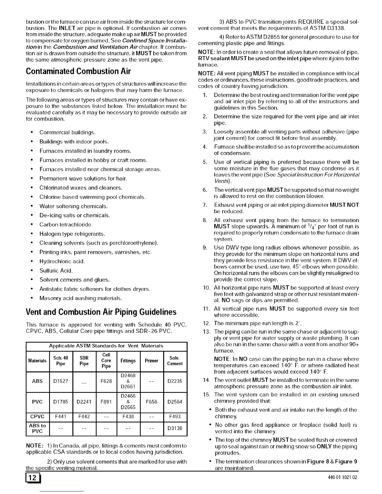
This furnace is approved for venting with Schedule 40 PVC,
CPVC, ABS, Cellular Core pipe fittings and SDR-26 PVC.
Applicable ASTM Standards for Vent Materials
Cell
Sch. 40 SDR Solv.
Core Fittings Primer
Materials Pipe Pipe Pipe Cement
D2468
ABS D1527 F628 & -- D2235
D2661
D2466
PVC D1785 D2241 F891 & F656 D2564
D2665
CPVC F441 F442 -- F438 -- F493
ABS to
.......... D3138
PVC
NOTE: 1) In Canada, all pipe, fittings & cements must conform to
applicable CSA standards or to local codes having jurisdiction.
2) Only use solvent cements that are marked for use with
the specific ventinq, material.
12.
13.
The minimum pipe run length is 2'.
The piping can be run in the same chase or adjacent to sup-
ply or vent pipe for water supply or waste plumbing. It can
also be run in the same chase with a vent from another 90+
furnace.
NOTE: In NO case can the piping be run in a chase where
temperatures can exceed 140 ° F. or where radiated heat
from adjacent surfaces would exceed 140 ° F.
14. The vent outlet MUST be installed to terminate in the same
atmospheric pressure zone as the combustion air inlet.
15. The vent system can be installed in an existing unused
chimney provided that:
• Both the exhaust vent and air intake run the length of the
chimney.
• No other gas fired appliance or fireplace (solid fuel) is
vented into the chimney.
• The top of the chimney MUST be sealed flush or crowned
up to seal against rain or melting snow so ONLY the piping
protrudes.
• The termination clearances shown in Figure 8 & Figure 9
are maintained.
44001 102102