forthe unit maximum amps stated on the rating plate. Add the full
load amps for potential field-installed accessories such as elec-
tronic air cleaners and humidifiers that would receive power from
the furnace control. The furnace control is rated for a maximum of
1.0 amps combined for EAC and HUM. Consult NEC or local
codes for proper wire and circuit sizing.
NOTE: Furnace will not have normal operation if line polarity is re-
versed. Check ALL field and control connections prior to opera-
tion.
J- Box Relocation
The j-box is installed on left side of casing. An alternate j-box
location on right side can be used.
1. Remove bag containing two hole plugs and two self tapping
screws from loose parts bag in blower compartment.
2. Remove two screws holding j-box to casing.
3. Install large hole plug from loose parts bag into the left j-box
location.
4. Clip wiretie holding j-box wires.
5. Move j-box to alternate location and attach using two self
tapping screws from bag.
6. Apply two hole plugs from bag at left j-box location.
Thermostat
Thermostat location has an important effect on the operation of the
unit. Follow instructions included with thermostat for correct
mounting and wiring.
Low voltage connections to furnace must be made on terminal
board of furnace control.
Set thermostat heat anticipator in accordance with the Technical
Support Manual.
Heat anticipator setting will need to be measured if 24VAC humidi-
fier is installed. Measure currentin series from R to W at the ther-
mostat. Be sure 24VAC humidifier is wired up to control. Allow
furnace to operate for 2 minutes before recording the AC amper-
age reading. Set anticipator on thermostat to recorded value.
Optional Equipment
All wiring from furnace to optional equipment MUST conform to lo-
cal codes or, in the absence of local codes with the latest edition of
The National Electric Code, ANSI NFPA 70 and/or The Canadian
Electric Code CSA C22.1. Install wiring in accordance with
manufacturer's instructions. The wiring MUST have a minimum
temperature rating of 105 ° C.
Humidifier/Electronic Air Cleaner
The furnace is wired for humidifier and/or electronic air cleaner
connection.
REDUCED FURNACELIFE HAZARD
Failure to follow caution instructions may result in
reduced furnace life.
Do NOT exceed 115V/1.0 amp. maximum current
load for both the EAC terminal and the HUM
terminal combined.
HUMIDIFIER- The HUM (115) is energized when the pressure
switch closes on a call for heat. The HUM is energized when
the inducer is enerqized.
ELECTRONIC AIR CLEANER - EAC is energized when there
is a blower speed call, except is NOT energized when blower
operates in the hard-wired continuous fan mode.
Furnace Control
The furnace control is preset at the factory with a fixed blower ON
delay of 30 seconds in the heating mode. The blower OFF timing is
preset at 140 seconds. If desired, the fan OFF delay can be reset to
obtain the longest delay times while still maintaining comfort lev-
els. See "Furnace Wiring Diagram".
Electrical Connections
NOTE: Junction Box can be _//
mountedtoeithertheleftorright j
side.
:z z W
_:_, Models may
J have1or2
((_"%) ' pressure
\ _._________________d% _ switches
I TerminalBoard
NOTE: 115 VAC/BOHz/single-phase
Operating voltage range*: 127 VAC max, 104 VAC rain.
Permissible limits of voltaqe at which unit will operate satisfactorily
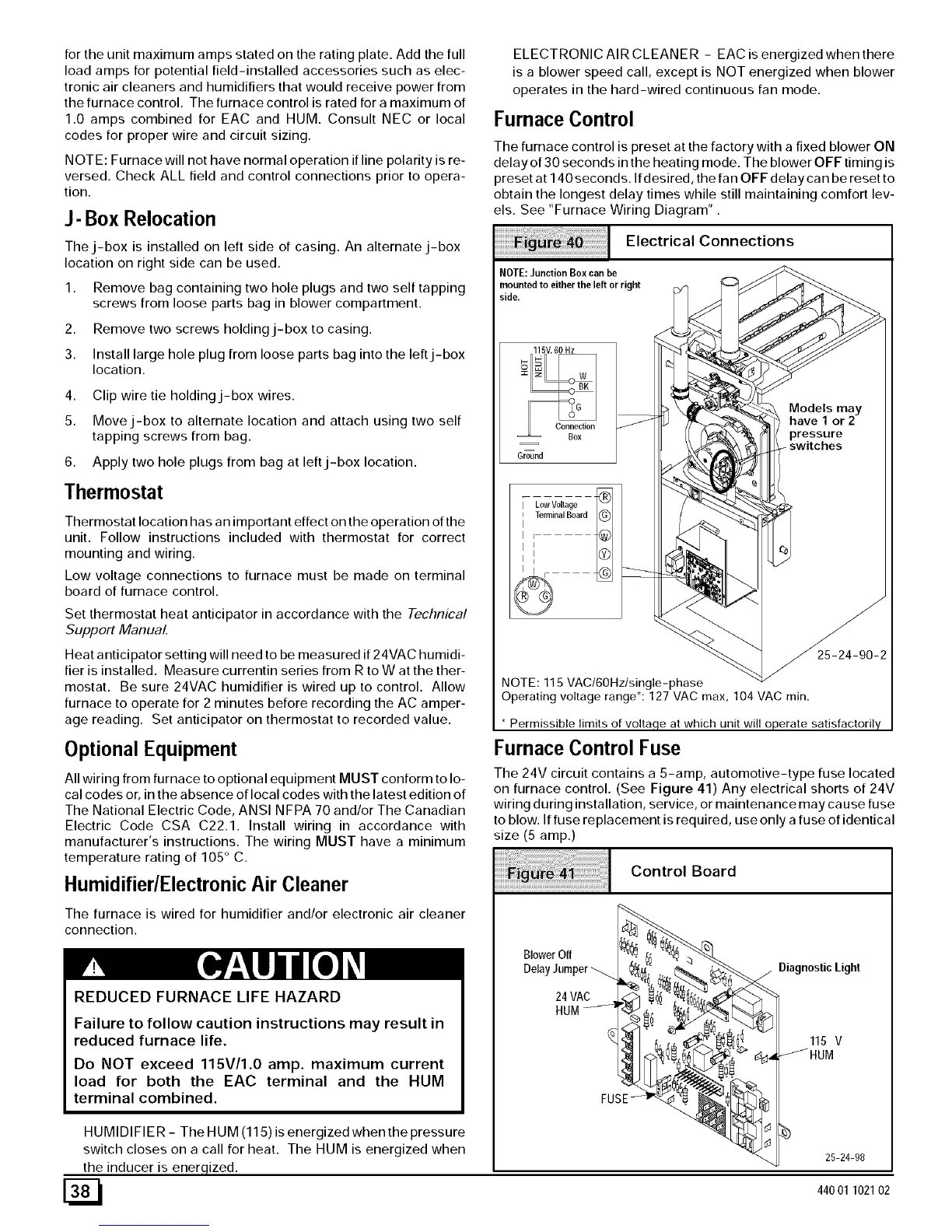
Furnace Control Fuse
The 24V circuit contains a 5-amp, automotive-type fuse located
on furnace control. (See Figure 41) Any electrical shorts of 24V
wiring during installation, service, or maintenance may cause fuse
to blow. If fuse replacement is required, use only a fuse of identical
size (5 amp.)
Control Board
BlowerOff
DelayJumper
24 VAC
HUM
DiagnosticLight
115 V
25-24-98
44001 102102