G
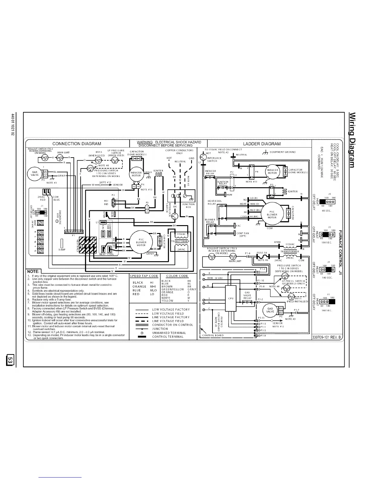
CONNECTION DIAGRAM WARNING: ELECTRICAL SHOCK HAZARD
DISCONNECTBEFORESERVICING LADDER DIAGRAM z oo
m _OO
ROLLOUT SWITCH 1 TO2 COPPER CONDUCTOR S O O
TO 115VAC FIELD DISCONNECT **qrr
INSERIESDEPENDING LP PRESSURE CAPACITOR " " OT /NE UTRAL /_
ONMODEL MAIN LIMIT BVSS SWITCH ONLY ,_H NOTE #2 EQUIPMENT GROUND O O O
ro-"4V_- ,..u.°,,w....°, .OT..UT--"°, .8.--,+
--o _ L 2_
NOTE #8 l | | _r_>
' ,--_,_'_ ' i_ _ _' 'P _ __ _ ..
/ .... _ I _',,._J$_'E_S--U_'ESW_TC--H---- ¥ ' I_NITER _. I -- I'_INDUCER 2 P_ (%%ERR)I_IcA_Ac'T°R _
[ ,,?As__I__ZI_BL_ ¥ _TO_,NSER,ES I 'NDU_R_" nnn _ " W RELAY P_ P_ _SOMEMODELS_ _ _o_0_
,..j_ _.,,.V,--,--GRN'_--I"_li' °.END,N_ONMODEL_'MOTOR' ,_,,00_ °.,W',o-. k_---_ _ ' __ _ °_°'_"
NOTE #31 / I NOTE#12 _ I
_. _W_SENSOR []_P4 I | _ IIG#NIT_Ov N I NOTE #'3 f._ _
_HO_- J._a__,_'G'TERN ,,
m I I00 180
.... I / II ,NOIld:::--I I _4-- UNC_ON HEAT_OOL
RELAY -- HEAT MHI (O)
o ,0o%o / / II _-__ _ B. 0ox _-- . _0 ,40
_nI i m_ M r_ 60SEC
_r_ __ I / II , ×. _, El-- =sJ. , ,MLO_0L,_..... _,_,>
....... )
> _o ,4o _ I I II I _u _l _w_ _LOWE.
< _0 W _ COOL 0
_LOWERl ''z_" t, _ ..... / -It =
_ ÷__1_/ II _ LI_--__14__1 _ RELAY IN " _ IN
_ _ _.-,_ _ __ ,_ i i---__ EAC _]= o ,,
__ _ _ '_ _ _ _°R_, __ CI_T_N co. N
-'_' U _Nd ,_', ,-J"_'_t.--,L_,;;;TO.''} _ i _ m°
_--_ S-AMP _ !T _ _ i 24VAC
HEAT COOL _ _ __w_/,_
I TRANSFORMER
ON MODEL PI 6 FUSE SA I
W MAIN LIMIT NOTE #6 24VAC COM
.L O
R .......... P14 1 TO 2IN SERIES
1. Ifanyoftheodginalequipmentwireisreplaced .... ireratedl05°C. SPEEDTAPCODE COLORCODE II I,,o I/_E _> ,40,EC
2. Useonlycopperwirebetweenthedisconnectswitchandthefumace _ M 24VAC
BLACK BK P SS SWITCH I
_unc,on,ox B_AC. .1 BLUE BL I , LL _/ :_P_'SD0.O.LY,'.
3. This wire must be connected to furnace sheet metal for control tOproveflame. ORANGE MHI BROWN BR I_ I P18 NOTE#8 _ .....
4. Symbois are eiectricalrepresentationonly. BLUE MLO GREENMELLOW GRNIY _ i _ _ ._
ORANGE O I GAS I \ U-"=--__--U........ ,
5. Solid lines inside circuit board are printed circuit board traces and are RED LO RED R I VALVE _ I O J1
not depicted as shown in the legend. WHITE W y CPU RELAY P12 _B\TS_
6. Replace only with a 5 amp fuse. YELLOW Y
7. Blower motor speed selections are for average conditions, see I _ G "_) f-"_ I (FIELD INSTALLEE
installation instructions for details on optimum speed selection. I °lp _/_1 ,_
8. Factory connected when LP Pressure Switch and BVSS (Chimney LOW VOLTAG E F ACTOR Y _ -<
Adapter Accessory Kit) are not installed. -- _ 18o sEC
9. Blower off*delay, gas heating selections are (60, 100, 140, and 180) LOW VO LTAG E FIE LD I
seconds, cooling or heat pump 90 seconds. L INE VO LTAG E F AC TO RY I _ _ '
_ " NOTE #3
J0.1gnitionlockoutwilloccurafter four consecutive unsuccessful tdals for I I I LINE VOLTAGE FIELD _-_z = &_LD_
ignition. Control will auto-reset after three hours. CONDUCTOR ON CONTR OL _ _>p_ SENSOR
11.Bloverload.......... switches.t°rand ind........ t...... rain intemal But ...... t thermal _ JUNCTION _ _ _O_ ,_[2_*) P 11_.p1 S NOTE #12
12. Flame sensor: 0.7 RA D.C. minimum, 2.0 - 4.0 #A nominal. O U N MAR K E D T ER MINAL
13. Depending on model, P4 inducer motor leads may be in a single connector _::#) P1 9
or M_oquick connecters. I CONTROLTERMINAL 1 CONTROLBOARD 330709-101REV. 13,
3