Knock Outs
CUT HAZARD
Failure to follow this caution may result in personal
injury.
Sheet metal parts may have sharp edges or burrs.
Use care and wear appropriate clothing, safety
glasses and gloves when handling parts and
servicing furnaces.
Use a hammer and screwdriver to strike a sharp blow (see
Figure 4) directly to the knockout tie points or use a hammer in the
upper left corner of the desired knockout. Remove any burrs and
sharp edges.
Hammer and Screwdriver Used
for Knockout
/
25-40-06
I OTE: If a knockout does not come out after two sharp blows, pull
and snip as needed to remove the knockout.
Installation Positions
This furnace can be installed in an upflow, horizontal (either left or
right) or downflow airflow position. DO NOT install this furnace on
its back. For the upflow position, the return air ductwork can be at-
tached to either the left or right side panel and/or the bottom. For
horizontal and downflow positions, the return air ductwork must be
attached to the bottom. The return air ductwork must never be at-
tached to the back of the furnace.
Furnace Installation Considerations
The installation of the furnace for a given application will dictate the
position of the furnace, the airflow, ductwork connections, vent and
combustion air piping. Consideration must be given to the follow-
ing:
Condensate Trap and Drain Lines
The supplied condensate trap must be attached to the furnace
side panel on either the left or right side. For horizontal installa-
tions, the drain trap is vertically attached to the side panel below
the furnace. A minimum clearance of 6" below the furnace is re-
quired for the condensate trap. Downward slope of the conden-
sate drain line from the condensate trap to the drain location must
be provided. Adequate freeze protection of the drain trap and the
drain line must be provided. See "Condensate Drain Trap"section
for further details.
Leveling
Proper leveling of the furnace must be provided to insure proper
_e of the condensate from the furnace. The furnace must be
44001 102102
level to within 1/4" from front to back and from side to side for upflow
and downflow installations or top to bottom for horizontal installa-
tions.
Vent and Combustion Air Connections
On the Dual Certified furnace, the vent and combustion air pipes
attach to the furnace through the top panel for the upflow and hori-
zontal installations. For the downflow installation, the vent and
combustion air pipes attach to the furnace through the alternate
locations on the furnace side panels.
Note: On the Direct Vent furnace, the vent pipe attaches to the fur-
nace through the side panels. The combustion air pipe attaches to
the top panel or to the alternate location on the side panel.
On the Single Pipe furnace, the vent pipe attaches to the furnace
through the furnace side panels.
Note: Repositioning of the combustion blower is required for the
vent pipe connection to the furnace through the "right side" panel.
See "Vent and Combustion Air Piping"section for further details.
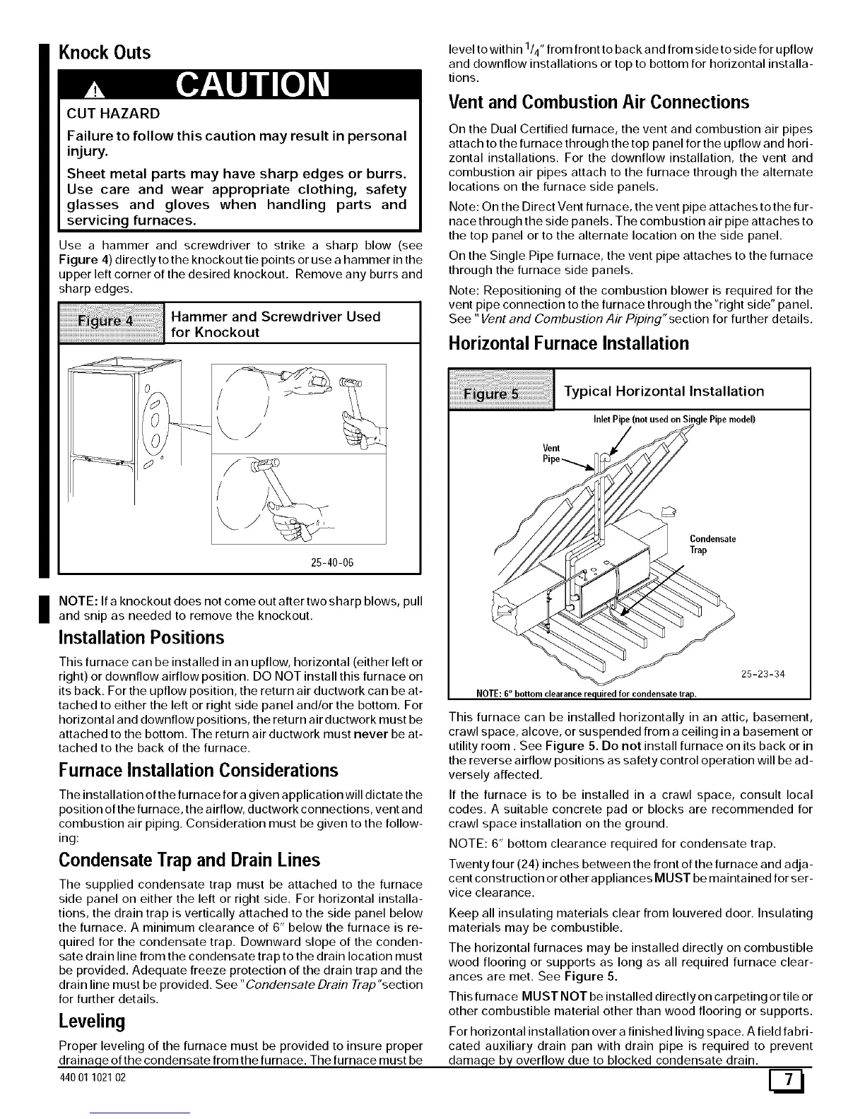
Horizontal Furnace Installation
Vent
Typical Horizontal Installation
Inlet Pipe (not used on Single Pipe model)
Condensate
Trap
25-23-34
NOTE: 6"bottomclearancerequiredfor condensatetrap.
This furnace can be installed horizontally in an attic, basement,
crawl space, alcove, or suspended from a ceiling in a basement or
utility room. See Figure 5. Do not install furnace on its back or in
the reverse airflow positions as safety control operation will be ad-
versely affected.
If the furnace is to be installed in a crawl space, consult local
codes. A suitable concrete pad or blocks are recommended for
crawl space installation on the ground.
NOTE: 6" bottom clearance required for condensate trap.
Twenty four (24) inches between the front of the furnace and adja-
cent construction or other appliances MUST be maintained for ser-
vice clearance.
Keep all insulating materials clear from Iouvered door. Insulating
materials may be combustible.
The horizontal furnaces may be installed directly on combustible
wood flooring or supports as long as all required furnace clear-
ances are met. See Figure 5.
This furnace MUST NOT be installed directly on carpeting or tile or
other combustible material other than wood flooring or supports.
For horizontal installation over a finished living space. A field fabri-
cated auxiliary drain pan with drain pipe is required to prevent
damn eq___ overflow due to blocked condensate drain.