3. Combustion & Ventilation Air
For Single PipeInstallation
When the installation is complete, check that all appliances have
adequate combustion air and are venting properly. See Venting
And Combustion Air Check in "4. Gas Vent Installation"Section in
this manual.
CARBON MONOXIDE POISONING HAZARD.
Failure to provide adequate combustion and
ventilation air could result in death or personal
injury.
Use methods described here to provide
combustion and ventilation air.
Furnaces require ventilation openings to provide sufficient air for
proper combustion and ventilation of flue gases. All duct or open-
ings for supplying combustion and ventilation air must comply with
the gas codes, or in the absence of local codes, the applicable na-
tional codes.
Combustion and ventilation air must be supplied in accordance
with one of the following:
1. Section 8.3, Air for Combustion and Ventilation, of the National
Fuel Gas Code, (NFGC), ANSI Z223.1-2002/NFPA 54-2002
in the U.S.,
2. Sections 7.2, 7.3, 7.5, 7.6, 7.7, and 7.8 of National Standard of
Canada, Natural Gas and Propane Installation Code
(NSCNGPIC), CSA B149.1-05 in Canada,
3. Applicable provisions of the local building code.
Outdoor Combustion Air Method
A space having less than 50 cubic feet per 1,000 BTUH input rating
for all gas appliances installed in the space requires outdoor air for
combustion and ventilation.
Air Openings and Connecting Ducts
1. Total input rating for all gas appliances in the space MUST be
considered when determining free area of openings.
2. Connect ducts or openings directly to the outdoors.
3. When screens are used to cover openings, the openings
MUST be no smaller than 1/4" mesh.
4. The minimum dimension of air ducts MUST NOT be less than
When sizing a grille, louver, or screen use the free area of
opening. If free area is NOT stamped or marked on grill or lou-
ver, assume a 20% free area for wood and 60% for metal.
Screens shall have a mesh size not smaller than 1/4".
Requirements
1. Provide the space with sufficient air for proper combustion and
ventilation of flue gases using horizontal or vertical ducts or
openings.
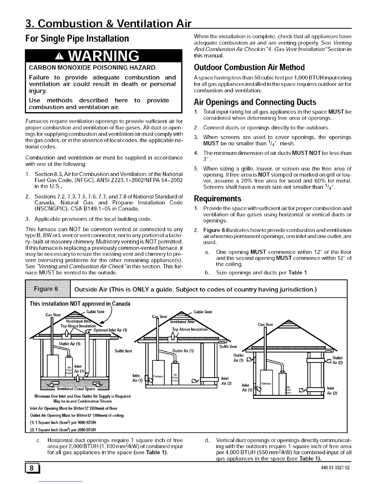
2. Figure 6 illustrates how to provide combustion and ventilation
air when two permanent openings, one inlet and one outlet, are
used.
This furnace can NOT be common vented or connected to any
type B, BW or Lvent or vent connector, nor to any portion of a facto-
ry- built or masonry chimney. Multistory venting is NOT permitted.
If this furnace is replacing a previously common-vented furnace, it
may be necessary to resize the existing vent and chimney to pre- a. One opening MUST commence within 12" of the floor
vent oversizing problems for the other remaining appliance(s), and the second opening MUST commence within 12" of
See "Venting and Combustion Air Check"in this section, This fur- the ceiling.
nace MUST be vented to the outside, b. Size openings and ducts per Table 1.
Outside Air (This is ONLY a guide. Subject to codes of country having jurisdiction.)
ThisinstallationNOTapprovedin Canada
GasVent
GableV_
(1)
Soffit Vent
Inlet
Air(1)
MinimumOne Inletand OneOutlet Air Supply is Required
May be in andCombination Shown
Inlet Air OpeningMust beWithin12"(300mm)of floor
OutletAir OpeningMustbeWithin12"(300mm)of ceiling
(1) 1 SquareInch (6cm2) per 4000 BTUH
(2) 1 Square Inch(6cm2) per 2000 BTUH
G Vent _Gable
Vent
ual_ventilated Attic_
/11 _ TopAboveInsulatio_
I/ SoffitVent
I "etAi"l' Out,o,'=
II _ Air (1)
Furnace G_
_',, _ _ _ Inlet
"" Air (2) Inlet
Air(1)
ED
Horizontal duct openings require 1 square inch of free
a 2
rea per 2,000 BTUH (1,100 mm /kW) of combined input
for all gas appliances in the space (see Table 1).
d.
Vertical duct openings or openings directly communicat-
ing with the outdoors require 1 square inch of free area
e 2
p r 4,000 BTUH (550 mm /kW) for combined input of all
gas appliances in the space (see Table 1).
44001 102102