InCanada,provincialcodesmaygoverninstallationofswitch.
Checkwithgoverningauthorities.
Changing Orifices for High Altitude
ELECTRICAL SHOCK, FIRE OR EXPLOSION
HAZARD
Failure to properly install orifices could result in
death, personal injury and/or property damage.
Turn OFF electric power (at disconnect) and gas
supply (at manual valve in gas line) when installing
orifices. Installation of orifices requires a qualified
service technician.
2. Turn OFF gas supply to all appliances and start furnace.
Example
.oturo,0ast .oo'Secondst 'imePerCubict "*°Per
BTU Content PerHour Footin Seconds Hour
1,000 3,600 48 75,000
1,O0O x 3,600 + 48 = 75,000 BTUH
3. Time how many seconds it takes the smallest dial on the gas
meter to make one complete revolution. Refer to Example.
4. Relight all appliances and ensure all pilots are operating.
NOTE: If meter uses a 2 cubic foot dial, divide results (seconds) by
two.
FinalCheck
NOTE: Main burner orifices can be changed for high altitudes.
1. Disconnect gas line from gas valve.
2. Remove manifold from furnace.
3. Remove the orifices from the manifold and replace them
with properly sized orifices.
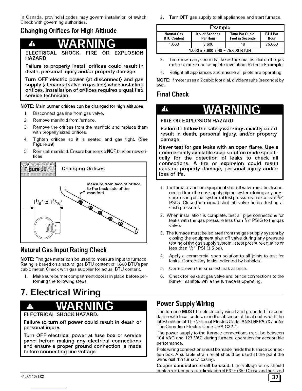
4. Tighten orifices so it is seated and gas tight. (See
Figure 39)
5. Reinstall manifold. Ensure burners do NOT bind on new ori-
fices.
11/8 " to 13/16"
Changing Orifices
Natural Gas Input Rating Check
Measure from face of orifice
to the back side of the
manifold.
2
NOTE: The gas meter can be used to measure input to furnace.
Rating is based on a natural gas BTU content of 1,000 BTU's per
cubic meter. Check with gas supplier for actual BTU content.
1. Make sure burner compartment door is in place before per-
forming the following steps.
7. Electrical Wiring
ELECTRICALSHOCK HAZARD.
Failure to turn off power could result in death or
personal injury.
Turn OFF electrical power at fuse box or service
panel before making any electrical connections
and ensure a proper ground connection is made
before connecting line voltage.
44001 102102
FIRE OR EXPLOSION HAZARD
Failure to follow the safety warnings exactly could
result in death, personal injury, and/or property
damage.
Never test for gas leaks with an open flame. Use a
commercially available soap solution made specifi-
cally for the detection of leaks to check all
connections. A fire or explosion could result
causing property damage, personal injury and/or
loss of life.
1. The furnace and the equipment shut off valve must be discon-
nected from the gas supply piping system during any pres-
sure testing of that system at test pressures in excess of 1/2"
PSIG. Close the manual shut-off valve before testing at
such pressures.
2. When installation is complete, test all pipe connections for
1 ,
leaks with the gas pressure less than /2' PSIG to the gas
valve.
3. The furnace must be isolated from the gas supply system by
closing the equipment shut off valve during any pressure
testing of thegas supply system at test pressure equal to or
less than 1/2' PSI (3.5 pa).
4,
5.
Apply a commercial soap solution to all joints to test for
leaks. Correct any leaks indicated by bubbles.
Correct even the smallest leak at once.
6. Check for leaks at gas valve and orifice connections to the
burner manifold while the furnace is operating.
Power SupplyWiring
The furnace MUST be electrically wired and grounded in accor-
dance with local codes, or in the absence of local codes with the
latest edition of The National Electric Code, ANSI N FPA 70 and/or
The Canadian Electric Code CSA C22.1.
The power supply to the furnace connections must be between
104 VAC and 127 VAC during furnace operation for acceptable
performance.
Field wiring connections must be made inside the furnace connec-
tion box. A suitable strain relief should be used at the point the
wires exit the furnace casing.
Copper conductors shall be used. Line voltage wires should
conform to temperature limitation of 63 ° F (35 ° C) rise and be sized