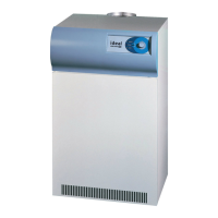
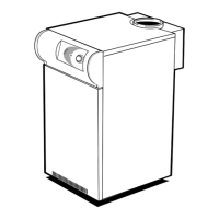
8 SITE ASSEMBLY - 600KW Vertical Boiler
9 SITE ASSEMBLY - 600KW HORIZONTAL BOILER
Note.
1. To aid the assembly procedure, on the ow &
return manifolds and the ow & return spools, the
anges are left loose for site welding.
2. The double M/F elbows (16) are to enable ease of
t and squareness.
LEGEND
1. Insulated boiler casing (c/w feet).
2. 80 nom. bore elbow.
3. Flow manifold (long).
4. Flow and return headers.
5. Flexible bellows unit.
6. Blank ange.
7. Gas header complete with gas cocks.
8. Rc 1
1
/2 union elbows.
9. Space nipple.
10. Flow and return spools.
11. Rc1
1
/2 elbow.
12. Space nipple.
13. Short space nipple.
14. Main gas cock (not shown).
15. Rc 2 twin elbow (with two hex bushes).
16. 1
1
/2 M/F elbow.
17. Return manifold (short).
Note.
1. To aid the assembly procedure,
on the ow & return manifolds
and the ow & return spools,
the anges are left loose for site
welding.
2. The double M/F elbows (12)
are to enable ease of t and
squareness.
LEGEND
1. Insulated boiler casing (c/w feet).
2. 125 nom. bore elbow.
3. Flow manifold (long).
4. Flow and return headers.
5. Flexible bellows unit.
6. Blank ange.
7. Gas header complete with gas cocks.
8. Rc 1
1
/2 union elbows.
9. Short space nipple.
10. Main gas cock (not shown).
11. Rc 2 twin elbow (with two hex bushes).
12. 1
1
/2 M/F elbow.
13. Return manifold (short).
INSTALLATION

 Loading...


