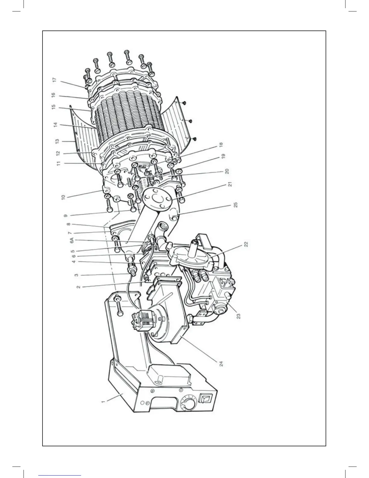
15 MODULE ASSEMBLY - Exploded View
LEGEND
1. Control chassis assembly
2. Multi-hole plate and cork
gaskets
3. Safety temp. limiter pocket
4. Sqaure to round casting
5. Ignition electrode
6. Burner cork gasket
6A. Burner bre gasket
7. Flow header
8. Flow header gasket
9. Burner
10. Top cover plate
11. Cover plate gasket
12. Top tube plate
13. Gas distribution screen
14. Finned copper tubes
15. Bottom tube plate
16. Cover plate gasket
17. Bottom cover plate
18. Sight glass
19. Flame sensor
20. Return header gasket
21. Return header
22. Gas / air control
23. Gas valve
24. Fan assy.
25. Thermostat pocket
Note. Items 22 & 23 supplied as
an assembly.
ASSEMBLY
 Loading...