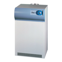
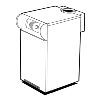
PACKAGING
The boiler casing is supplied complete with insulation and
feet, strapped to a packaging base and shrink-wrapped.
Boilers up to and including 150kW will have their water and
gas headers packed and shrink-wrapped with the casing.
Boilers of 200kW and above will have their water and gas
headers supplied on a pallet, shrink-wrapped. The water
header bellow units, anges, gaskets etc., will be packed in
cartons in the bottom of the casing. The modules are supplied
individually packed on a packaging base.
FOUNDATION
An insulated foundation is NOT necessary, as the bottom
of the boiler casing will not exceed a temperature of 80°C.
(176°F.).
The foundation MUST be at and level, reproof, dust free
and capable of supporting the weight of the WET boiler.
CASING AND CONNECTION
A 22mm copper street elbow is supplied in the water header
hardware pack, for connection to the casing drain point. This
elbow can be tted in any direction and the compression nut
tightened. A suitable drain should be connected to the elbow.
Refer to Frame 14.
Note. Condensation will only occur on warming up, when the
return water temperature is below 55°C. (131°F.) - the water
dew point.
The boiler casing can now be placed in position.
N.B. EXTREME CARE MUST BE TAKEN WHEN HANDLING
THE CASING, WHICH IS FITTED WITH AN ALUMINIUM
FACED, INSULATING CLADDING. THIS CLADDING CAN BE
KEPT CLEAN BY WIPING WITH A DAMP CLOTH.
ASSEMBLING THE MODULE AND WATER HEADERS TO
THE BOILER CASING (REFER TO FRAMES 8, 9 & 14).
WARNING:
CRACKING MAY OCCUR IF THE FLOW AND RETURN
MODULE CASTINGS ARE OVER STRESSED.
The following procedure is to be adopted:
1. Ensuring all cables are held clear with the module
cover removed, t the module(s) to the casing but do
NOT tighten the four xing nuts.
2. For boilers over 150kW ONLY:
Screw the anged bellows unit into the internally threaded
branches of the water headers, using a wrench on the
hexagon at the end of the bellows to tighten in position.
When tight, the ange on the bellows should nish
approximately 470 mm (18
1/2
in.) away from the xed
anges, with the ange holes in a vertical and horizontal
attitude - refer to Frame 14.
UNDER NO CIRCUMSTANCES MUST THE
FLANGE OR BELLOWS BE USED FOR
TIGHTENING
3. Secure the ow and return water headers to the modules
(rigid anges rst) using the gaskets and screws
provided, taking adequate precaution to support the
headers during assembly.
FOR 150kW ALTERNATIVE and 250kW V
boilers only
Ensure that the ange support bracket is tted to the water
header and module blanking plate.
Note: Care should be taken to avoid damage to the bellows
units whilst tightening the screws securing the bellow anges.
GAS HEADERS 100kW - 150kW boilers only:
Remove the adaptors from the exible gas hoses and screw
them to the elbows on the individual modules.
Offer up the gas header by lowering over the projecting studs
on the water ow header so that the gas inlet pressure test
point is at the top. Fasten with the nuts and washers provided.
Assemble the exible hoses to the gas header and the
individual modules , ensuring all connections are tight.
150kW A and boilers over 150kW
Remove the adaptors from the short exible gas hoses
and one of the adaptors from the long exible gas hoses.
Then assemble them to the elbows on the individual modules.
Remove the other adaptors from each of the long exible
gas hoses and x them to the appropriate cocks on the gas
header. (horizontal cocks on vertical models and vertical
cocks on horizontal models). Then screw the long exible gas
hoses back onto the adaptors.
Screw the short exible gas hoses to the appropriate gas
cocks on the gas header (vertical cocks on vertical models
and horizontal cocks in horizontal models).
Offer up the gas header so that it locates over the projecting
studs on the water ow header and the gas inlet pressure test
point is at the right hand end (horizontal boilers) or at the top
(vertical boilers). Fasten with the nuts and washers provided.
Assemble the exible gas hoses to the adaptors ensuring all
connections are tight.
ASSEMBLY
 Loading...