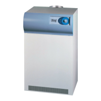
Note: The discharge from both types of system MUST
not allow recirculation of combustion products into the
boilerhouse or adjacent buildings.
Notes:
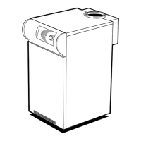
The draught at the boiler casing must be controlled between
neutral and 0.2 mbar (0.08 in. w.g.) negative irrespective of
the number of modules ring. The draught stabiliser must be
tted within 1 metre of the boiler casing.
To achieve the minimum neutral draught condition a vertical
ue length of 2 metres is needed plus whatever extra height
is necessary to overcome the resistance of any bend or duct
work between the boiler casing and the vertical ue.
Note: Air intake and discharge should be on the same
outside wall face. Design must comply with British Gas
requirements - refer page 5 and Publication IM/11.
3 APPLICATION OF DRAUGHT STABILISER - SINGLE BOILER INSTALLATION
4 FLUEING - GENERAL GUIDANCE BOILER INSTALLATION
All dimensions in millimetres (inches)
All dimensions in millimetres (inches)
GENERAL
 Loading...