SERVICING INSTRUCTIONS
IMPORTANT
In order to ensure safe and reliable operation of Ideal
Concord Super boilers it is essential that regular
maintenance be carried out by competent staff who have
received instruction in maintenance, fault nding and
commissioning procedures for this boiler series.
ANNUAL servicing is recommended.
BEFORE CARRYING OUT ANY SERVICING PROCEDURE:
1. Isolate the boiler electrical supply.
2. Turn off the gas service tap on the module being
serviced.
3. Be aware that the 4 mm pipes connecting the gas valve
to the gas/air control unit are factory sealed and MUST
NOT be disturbed.
The following procedure should be carried out annually.
Preparation for servicing.
Possible spares required:
Fan motor impellor housing gasket.
Round cork burner gasket.
Round foil-faced glass-bre gasket complete with ‘U’ shaped
extension.
Square cork fan outlet gaskets (2).
Ignition electrode with lead.
Flame sensing probe with lead.
1. Unscrew the two retaining screws from the front of the
orange cover and remove the cover.
2. Withdraw the multi-pin plug from the left-hand side of the
module and switch off the module on/off switch.
3. Unscrew the M5 screw at the right-hand side of the rear
control panel (see Frame 19) & swing the panel to the
left.
4. Disconnect the lead to the ignition electrode from Board
No. 29 control box and withdraw it through the cable tie
wrapped round the return elbow behind the gas valve.
5. Release the fan motor lead and mains harness lead from
the clip at the left-hand side underside of the fan plate.
6. Unfasten the plug and socket connection to the fan
motor.
7. Unfasten the plug and socket connection to the ame
sensor.
8. Undo the 6 mm suction sensing line union connections
at the ‘square to round’ casting and at the gas/air control
unit and remove the sensing line.
9. Undo the 6 mm pressure sensing line union connections
at the fan housing base and at the gas/air control unit and
remove the sensing line.
10. Undo the 3 elongated M8 nuts with slotted heads,
securing the fan assembly.
11. Remove the fan assembly, taking care not to damage the
fan impellor.
12. Disconnect the burner earth lead from the earthing post
at the left-hand rear side of the chassis.
13. Remove burner completed with its integral ignition
electrode.
Servicing the ignition electrode and burner
1. Brush the inside and outside of the burner, making sure
to clear any blockages in the burner.
2. If the burner shows any sign of deterioration it should be
replaced.
3. Inspect the ignition electrode. If it shows any sign of
erosion or if there is damage to the insulation or integral
lead, it should be replaced.
Undo the retaining nut and withdraw the electrode from
its housing. Fit new electrode.
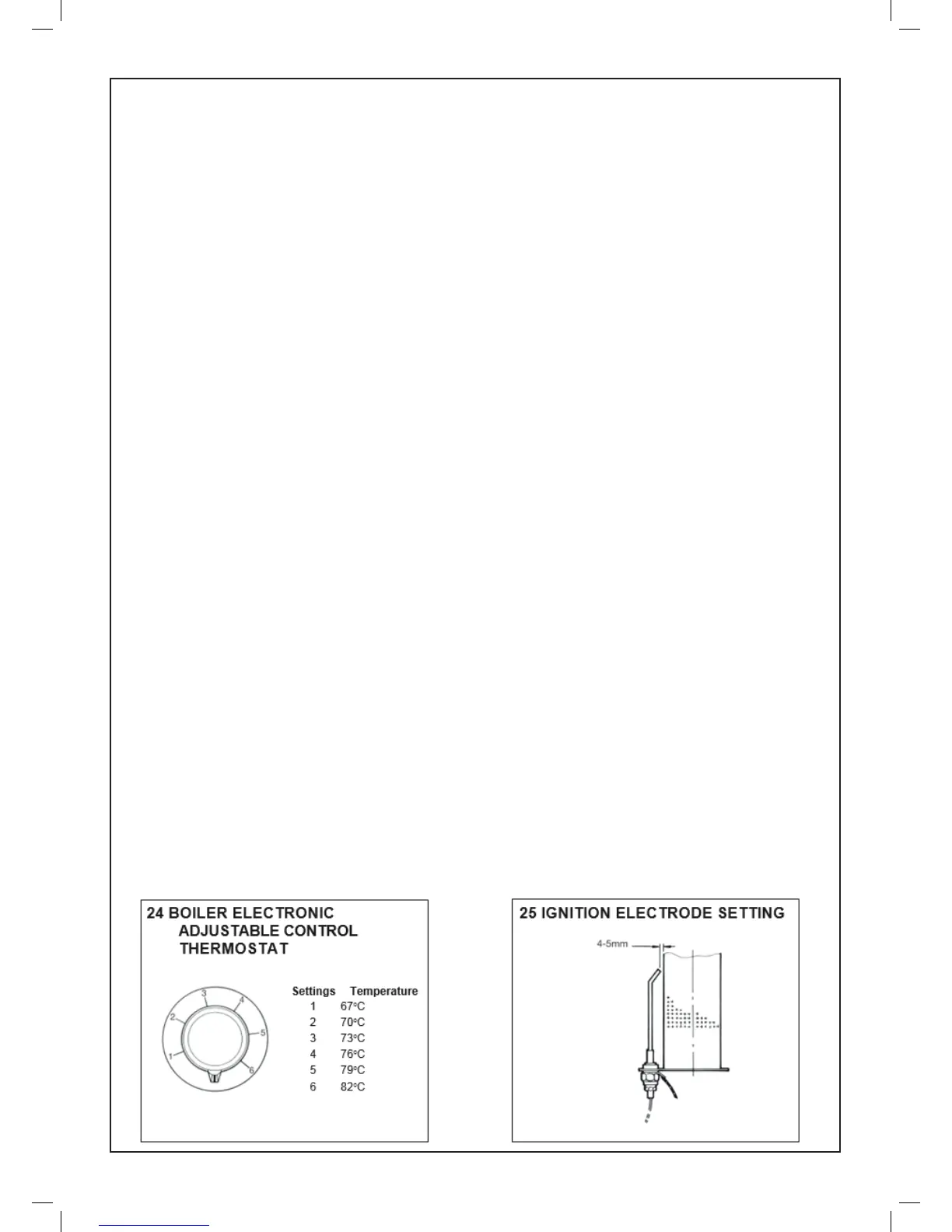
4. Check the spark gap and adjust, if necessary. It should
be 4-5 mm - see Frame 25.
Servicing the ame sensing probe
Undo the retaining nut and withdraw the probe. If it shows any
signs of erosion, damage to insulation or to the integral lead
IT MUST BE REPLACED.
Inspecting the nned tubes of the heat exchanger(s)
Inspect the DRY side of the heat exchanger nned tubes by
viewing through the burner opening, using an electric torch
and mirror.
In general, on intermittently operated systems, it will not be
necessary to undertake chemical cleaning more than once
every two years although, as mentioned above, the DRY side
should be examined at least once a year to assess the rate of
build up of debris.
When systems are operated virtually continuously, heat
exchangers should not exceed 3,000 hours ring time
between chemical cleaning. For instructions on chemical
cleaning, see relevant section.
SERVICING AND FAULT FINDING
 Loading...