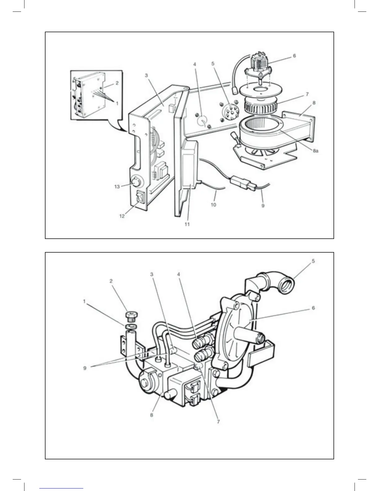
EasyManuals Logo

IDEAL Concord Super Series 4 50 V User Manual

IDEAL Concord Super Series 4 50 V
40 pages
To Next Page IconTo Next Page
To Previous Page IconTo Previous Page
Page #23 background imageLoading...
Page #23 background image
21
Concord Super Series 4 - Installation & Servicing
LEGEND
1. Injector washer
2. Injector
3. Gas outlet pressure test point
4. Gas/air suction pressure test point
5. Iron elbow - gas connection
6. Gas/air control
7. Gas inlet pressure test point
8. Gas valve
9. 4mm sensing line
Note. Items 6 & 8 supplied as an assembly
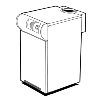
LEGEND
1. LED’s
2. Lockout reset button
3. PCB No. 28
4. Safety temperature limiter
5. Mains socket
6. Fan motor
7. Fan impellor
8. Fan scroll
8a. Fan gasket
9. Flame sensing lead
10. Ignition lead
11. PCB No. 29
12. On/Off switch
13. Thermostat knob
16 ELECTRICAL CONTROLS - Exploded View
17 GAS LINE
ASSEMBLY

Table of Contents

Questions and Answers:

Question and Answer IconNeed help?

Do you have a question about the IDEAL Concord Super Series 4 50 V and is the answer not in the manual?

IDEAL Concord Super Series 4 50 V Specifications

General IconGeneral
BrandIDEAL
ModelConcord Super Series 4 50 V
CategoryBoiler
LanguageEnglish

Related product manuals