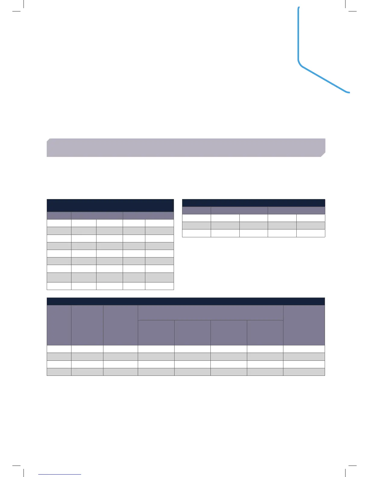
31
For concentric flue systems with elbows fitted, use the table to correct the maximum flue extension capability.
Alternatively use the table to design the flue system, deducting the individual resistance of components from
the maximum pressure drop allowed in the flue for that boiler. The maximum pressure drop allowed in the flue is
given below.
The maximum permissible flue lengths for each model are shown in Table 1 below, these lengths are inclusive of
the terminal resistance. The value shown is the maximum available length for extension. The equivalent length of
elbows is shown in Table 2.
FLUE RESISTANCES
FLUE SYSTEMS
TABLE 1 TABLE 2
MAX PERMISSIBLE EQUIVALENT FLUE LENGTH
(INC TERMINAL RESISTANCE) METRES
CONCENTRIC OPEN FLUE
Flue Size 80/125 100/150 80 100
Model
30/30P 42 - 65 -
40/40P 52 - 70 -
60/60P 7.5 30 25 -
80/80P 12 35 22 -
100 - 14.3 - 20
120 - 17.6 - 49
150 - 7.5 - 32
EQUIVALENT LENGTH OF ELBOWS (METRES)
CONCENTRIC OPEN FLUE
Size 80/125 100/150 80 100
45˚ 0.85 1.25 0.45 0.60
90˚ 1.6 1.9 1.0 1.0
EXAMPLES OF FLUE LENGTH CALCULATION
MODEL FLUE TYPE
MAX
PERMISSIBLE
EQUIVALENT
LENGTH
(TABLE 1)
ELBOWS
MAX
PERMISSABLE
STRAIGHT
LENGTH
TYPE
EQUIVALENT
LENGTH
(TABLE 2)
NO
TOTAL
EQUIVALENT
LENGTH
60 80/125 7. 5 90 1.6 2 3.2 4.3
60 100/150 30 90 1.9 2 3.8 26.2
80 80/125 12 90 1.6 3 4.8 7. 2
120 100/150 17.6 90 1.9 4 7.6 10.0
PERMISSIBLE FLUE LENGTH

 Loading...


