07
1
3
4
5
7
6
8
9
10
12
11
2
500
‘C’
850
59 59
Gas
Flow Return
299
206210-10155
‘B’
‘A’
155
81
68
Gas pipe
Flow/return
Condensate drain
Flue centre line
Flue centre line
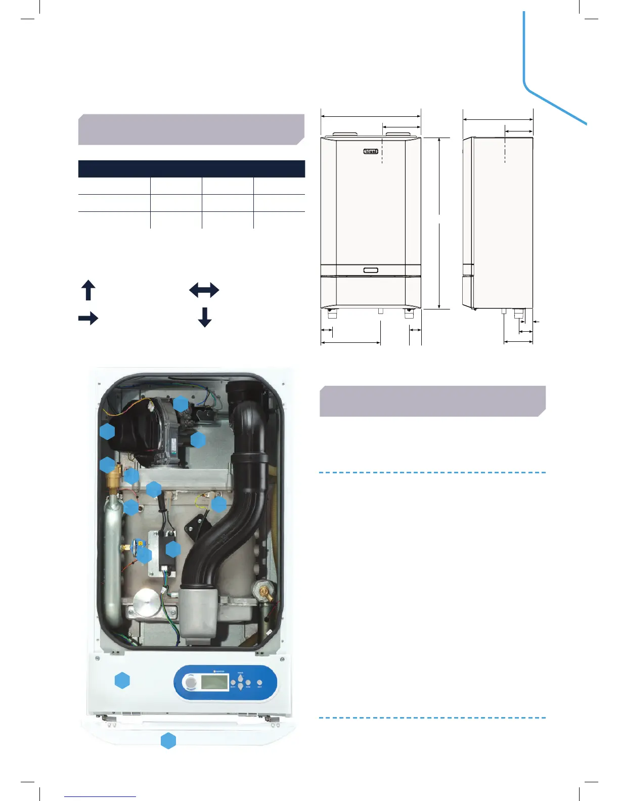
DIMENSIONS & CLEARANCES
BOILER ASSEMBLY
BOILER DIM A DIM B DIM C
30, 40, 60, 80 360 130 118
100, 120 520 226 118
150 610 233 120
The following minimum clearances must be
maintained for operation and servicing:
TOP: DEPENDENT
ON FLUE SIZE
SIDES: 25mm
FRONT: 450mm BOTTOM: 300mm
CLEARANCE BETWEEN MULTIPLE BOILER
INSTALLATIONS: 25mm
KEY
1. Auto Air Vent
2. Burner Fixings
3. Fan
4. Gas Valve
5. Venturi
6. Flow Thermistor
7. Ignitor Unit
8. Electrode Detection
9. Ignition Electrode
10. Fascia and Controls
11. Door Assembly
12. Water pressure sensor
INTERNAL VIEW
(80kW MODEL SHOWN)
All dimensions in mm
 Loading...


