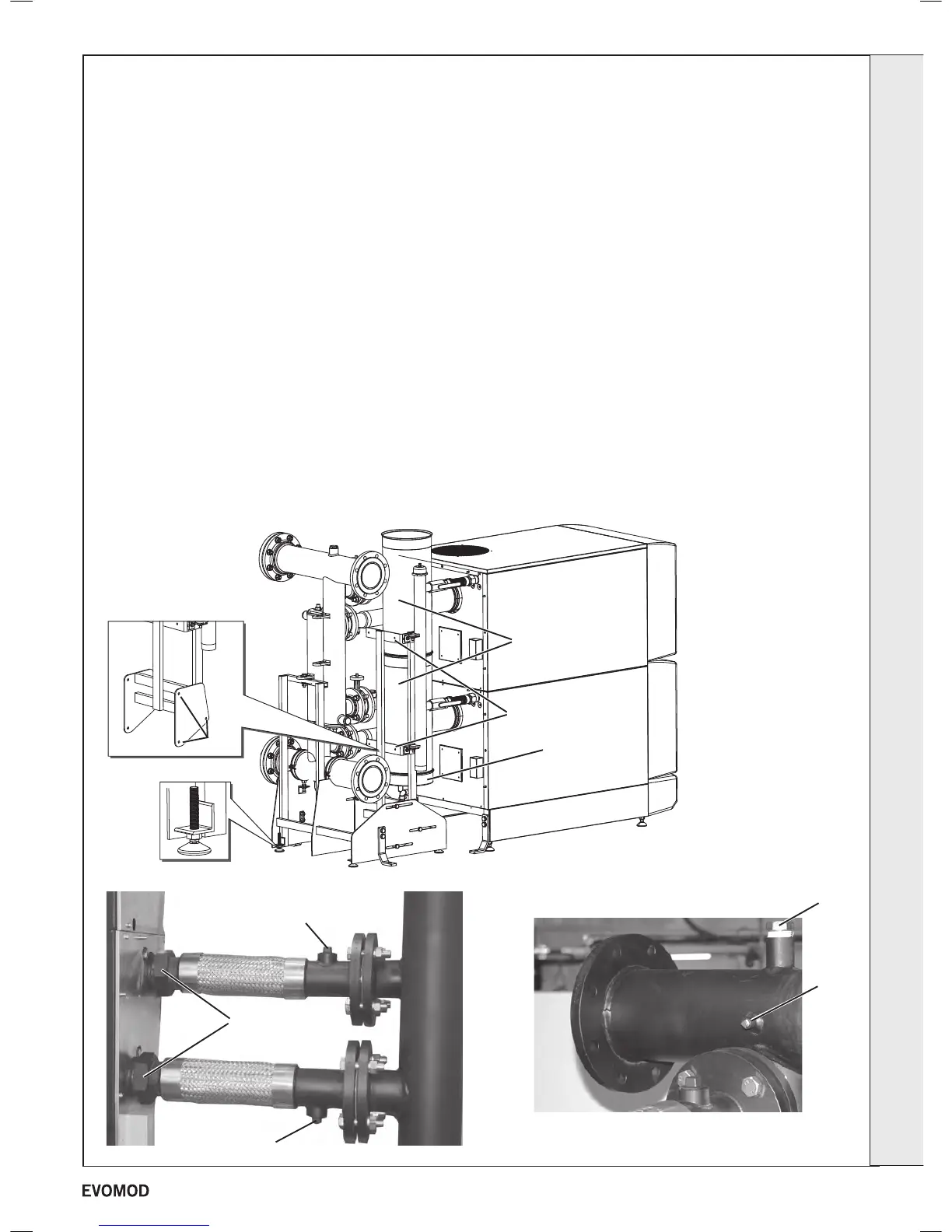
Flue header support frame
screws
Bottom
cap
T Pieces
Flue Support Brackets
Adjustable
feet
The ue header is supplied as standard with the boiler (not
250 model).
See table on page 5 for guidance on maximum permissible
ue duct system design
The water and gas header system is supplied as a fully
assembled self supporting unit capable of connecting the
water and gas services direct to the rear of the module/s.
500kW & 750kW (see Frame 17 for 1000kW)
1. Assemble the ue manifold T pieces (long legs point upwards),
ensuring the seals are tted and lubricated using the seal
lubricant provided.
2. Push the assembled T pieces into the boiler connections
ensuring the seals are tted and lubricated using the seal
lubricant provided.
3. Unpack and position the header assembly at the rear of the
boiler.
4. Use the adjustable feet to both level the unit and position the
unions adjacent to their respective module connections.
5. Connect each header ow & return exible hose connection
to the appropriate module male thread using the bre washer
provided. Note: A number of adjustments are available within
the header assembly to help align connections. These must be
secured after any adjustments.
6. An air vent point is provided in the top of the ow header and an
automatic air vent MUST be tted.
7. If the header kit used includes isolation valves, a pressure relief
valve MUST be tted to the 1” boss provided on the exible ow
pipe of each module.
8. A 1” boss is provided on the underside of the exible return pipe
to enable a drain valve to be tted.
9. The header thermistor MUST be tted to the boss provided on
the header ow pipe.
10. Connect each exible gas header pipe to the appropriate
module male thread. Note: A number of adjustments are
available within the header assembly to help align connections.
These must be secured after any adjustments.
11. Secure the ue manifold to the header frame with the 2 support
brackets provided. Note: The frame that supports the ue
manifold & gas header can move forwards or backwards for
adjustment.
12. Fit the bottom cap to the ue manifold & secure with one of the
locking bands provided. Use the remaining locking bands to
secure the ue manifold T pieces together. Note: This bottom
cap must be connected to a drain via a water trap using plastic
components only.
Refer to frames 1-4 for
dimensions.
The header ow and return
pipes are terminated with two
2
1
/2" PN16 anges (250 model)
and 5" PN16 anges (500, 750
and 1000 models). For 1000
models, the headers are bolted
together at the anges.
Flushing
If installing onto a new or
existing system it is strongly
recommended that the
system be thoroughly ushed
in accordance with the
requirements of BS:7593 before
connecting the boiler.
PRV 1" Boss
Header ow &
return connections
Auto air vent boss
Header
thermistor
boss
Drain valve boss
16
WATER AND GAS HEADER INSTALLATION
INSTALLATION
continued . . . . . .
19
- Installation & Servicing

 Loading...


