46
REMOVAL OF BURNER ASSEMBLY AND BURNER CLEANING
1. Refer to Frame 40.
2. Refer to Frame 45 for removal of fan/venturi.
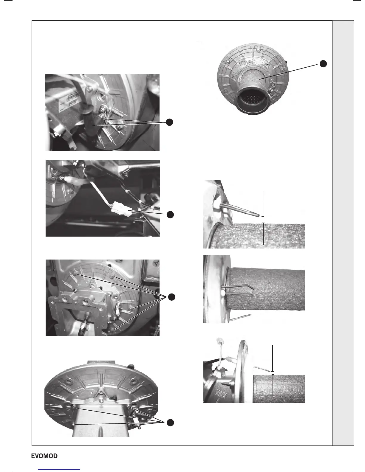
3. Disconnect the ignition lead cap, earth lead and sensing
lead ‘in line’ connector.
4. Remove the six nuts retaining the burner assembly and
carefully withdraw the assembly.
5. Remove the ve screws retaining the fan mounting manifold
and remove the manifold.
6. Carefully remove the burner, the burner can be cleaned
internally only using a soft brush and/or vacuum. The metal
bre outer surface MUST NOT BE BRUSHED. If the burner
shows signs of damage it must be replaced.
7. Inspect the ignition and detection electrodes for signs of
damage and check the dimensional relationship between
the electrodes and the burner surface (refer to photographs
for correct dimensions.
8. Re-assemble in reverse order replacing any seals/gaskets
which show signs of wear.
9. Refer to frame 39 for nal safety checks.
REPEAT PROCEDURE FOR SLAVE MODULE/S
Ignition electrode
Detection electrode
4
5
6
3
3
4.5mm
+
_
0.5mm
8mm
+
_
1mm
8mm
+
_
1mm
SERVICING
39
- Installation & Servicing

 Loading...


