7. Remove the four nuts and washers retaining the fan to the
burner mounting plate.
8. Remove the EMC lter bracket.
9. Remove the Module PCB to a safe place.
10. Carefully remove the fan assembly to a safe working area.
11. Inspect the fan and venturi and reassemble in reverse order
replacing any seals/gaskets which show signs of wear.
12. Refer to Frame 39 for nal safety checks.
REPEAT THE PROCEDURE FOR THE SLAVE MODULE/S
45
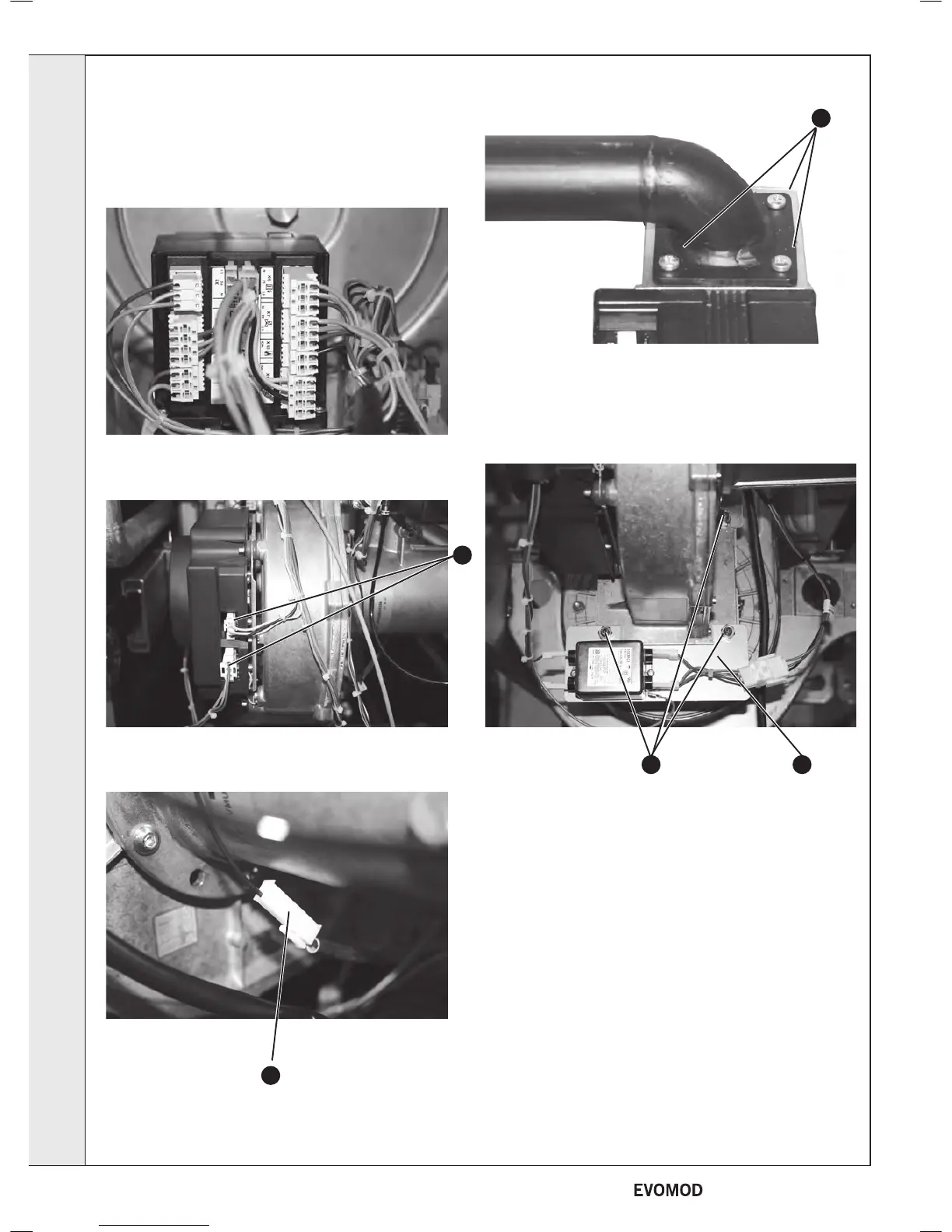
REMOVAL OF FAN / VENTURI FOR INSPECTION
1. Refer to Frame 40.
2. Remove the module front cover (refer to Frame 43).
3. Disconnect the electrical connections from the Module PCB.
4. Disconnect the electrical connections from the fan.
5. Disconnect the detector lead ‘in line’ connector.
6. Remove the four nuts retaining the gas pipe to the gas
control valve.
6
5
4
87
SERVICING
38
- Installation & Servicing

 Loading...


