50
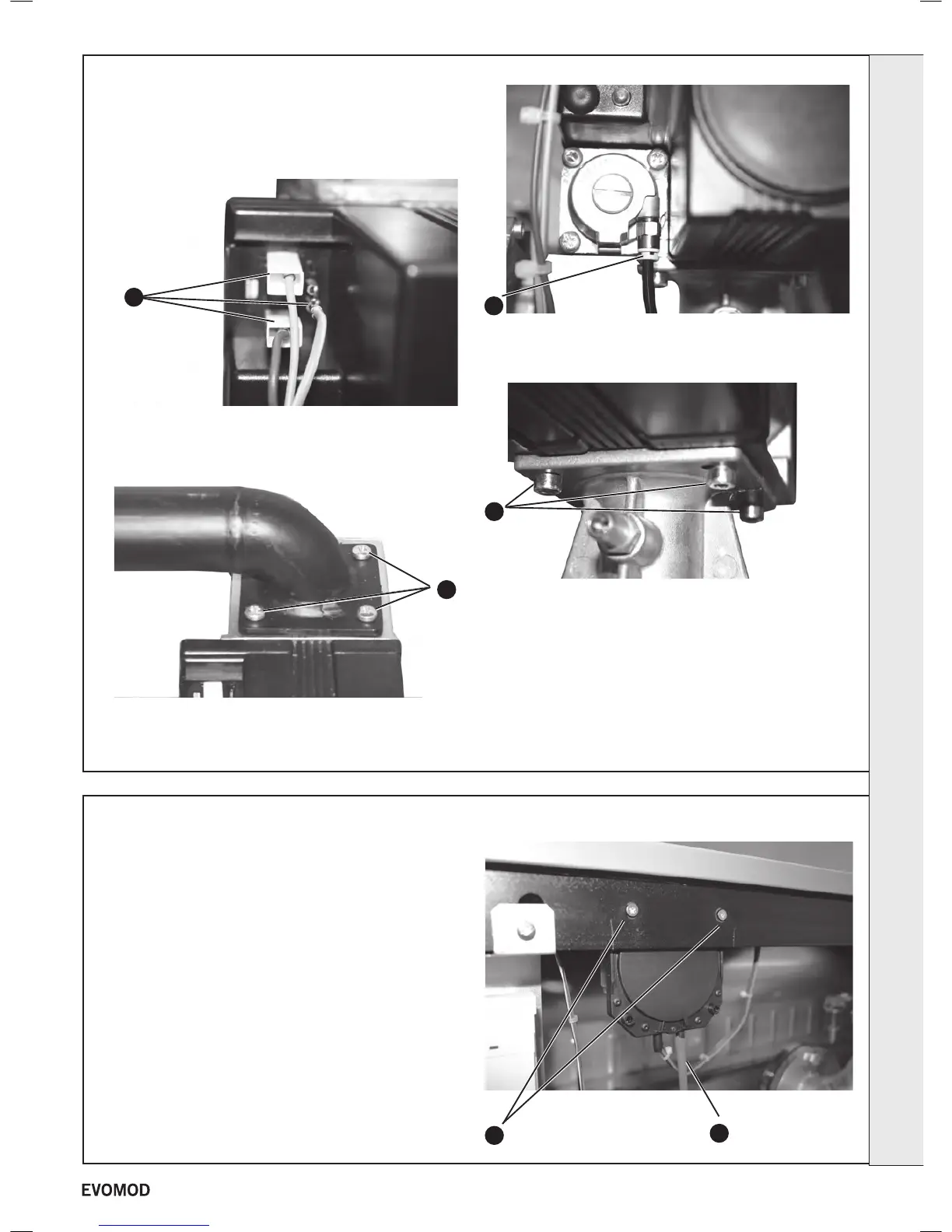
GAS VALVE
1. Refer to Frame 40.
2. Remove the module front cover (refer to Frame 44).
3. Remove the electrical connections.
4. Remove the four nuts retaining the gas pipe to the gas
control valve.
5. Remove the pressure sensing lead by lifting the white
sealing ring and pulling the black lead out.
51
CONDENSATE BLOCKAGE PRESSURE SWITCH
1. Refer to Frame 40.
2. Remove the module front cover (refer to Frame 44).
3. Remove the right hand side panel (refer to Frame 15)
4. Pull off the sensing tube at the pressure switch.
5. Remove the two pressure switch xing screws.
6. Remove the four socket cap screws retaining the gas valve
to the outlet ange.
7. Withdraw the gas valve taking care to retain the inlet
and outlet ‘O’ rings.
8. Fit the new gas valve (replace inlet/outlet ‘O’ rings if
showing signs of wear)
9. Re-assemble in reverse order.
10. Refer to instruction sheet with new gas valve for correct
setting procedure.
11. Refer to Frame 39 for nal safety checks.
4
3
5
6
5
4
Live
Earth
Neutral
SERVICING
41
- Installation & Servicing

 Loading...


