53
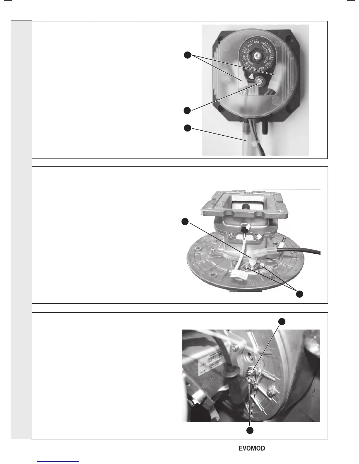
DETECTION ELECTRODE REPLACEMENT
1. Refer to Frame 40.
2. Remove the module front cover. Refer to Frame 44.
3. Remove the detection plug cap.
4. Remove the two cap screws retaining the detection
electrode and carefully withdraw the electrode.
5. Fit the new electrode and re-assemble in reverse order.
6. Refer to Frame 39 for nal safety checks.
54
IGNITION ELECTRODE REPLACEMENT
1. Refer to Frame 40.
2. Remove the module front cover (refer to Frame 44).
3. Remove the ignition plug cap and the earth connection.
4. Remove the two cap screws retaining the ignition electrode
and carefully withdraw the electrode.
5. Fit the new electrode and re-assemble in reverse order.
6. Refer to Frame 49 for nal safety checks.
3
4
3
4
52
CONDENSATE BLOCKAGE
PRESSURE SWITCH - Cont.
6. Remove the single cover xing screw and remove the
plastic cover.
7. Pull off the two electrical connections and transfer to the
new switch.
8. Re-assemble in reverse order ensuring the pressure pipe is
tted to the positive (+) connection on the pressure switch.
9. Refer to frame 39 for nal safety checks.
6
7
8
SERVICING
42
- Installation & Servicing

 Loading...


