60
BURNER REPLACEMENT
1. Refer to Frame 40.
2. Remove the module front cover (refer to Frame 44).
3. Remove all electrical connections from the Module PCB.
4. Remove the four screws retaining the control to the bracket.
5. Fit the new Module PCB, re-assembling in reverse order.
6. Refer to Frame 39 for nal safety checks.
61
MODULE PCB
1. Refer to Frame 40.
2. Remove the module front cover (refer to Frame 44).
3. Remove the fan assembly to a safe working area (Refer to
Frame 45).
4. Remove the burner (Refer to Frame 46)
5. Fit the new burner ensuring all seals and gaskets are
inspected for wear or damage and replaced accordingly.
6. Re-assemble in reverse order.
7. Refer to frame 39 for nal safety checks.
59
FAN REPLACEMENT
1. Refer to Frame 40.
2. Remove the module front cover (refer to Frame 44).
3. Remove the fan assembly to a safe working area (Refer to
Frame 45).
4. Remove the six venturi xing screws, remove venturi and t
to new fan.
5. Fit the new fan assembly and re-assemble in reverse order.
6. Refer to Frame 39 for nal safety checks.
4
4
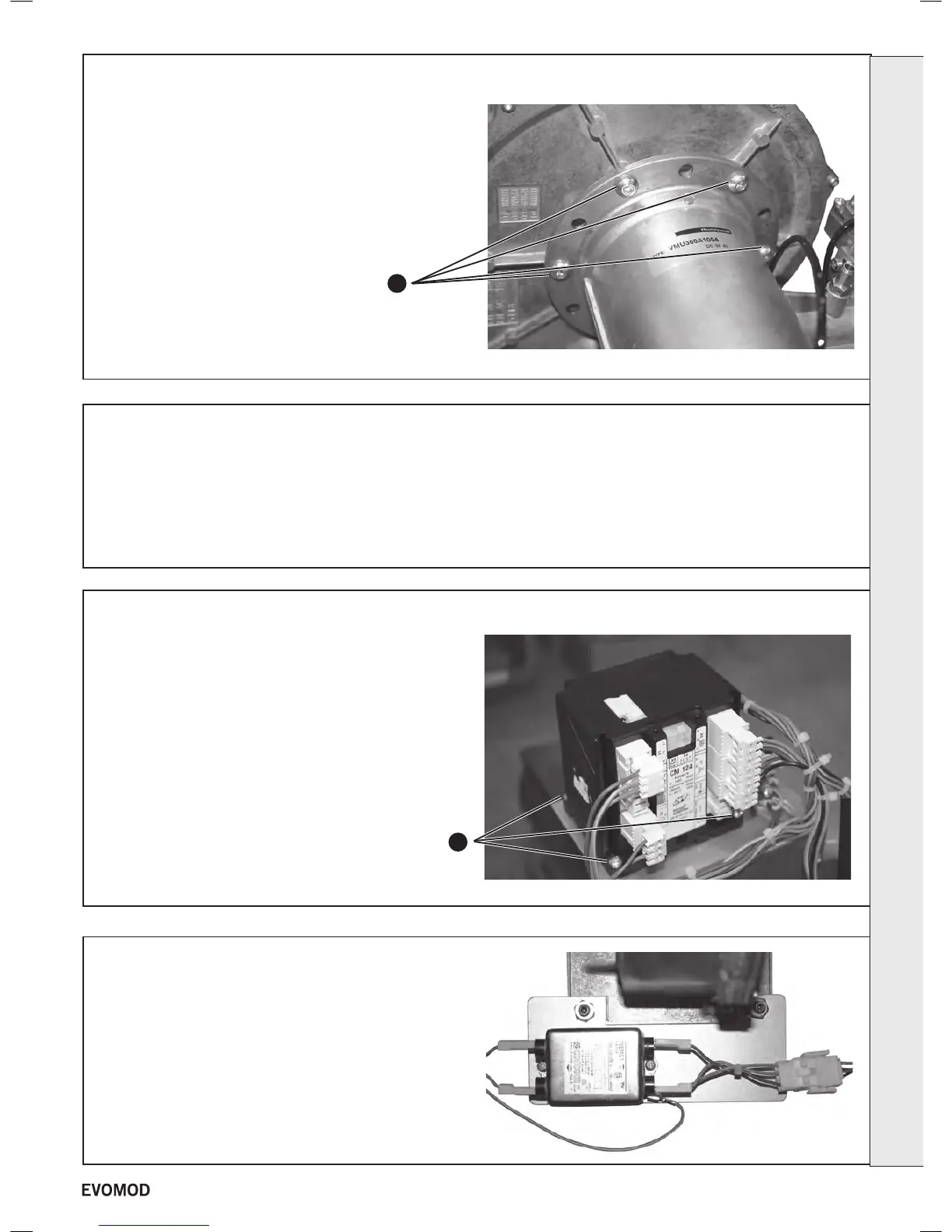
1. Disconnect the leads from the EMC lter.
2. Remove the two screws xing the EMC lter to the bracket.
3. Re-assemble in reverse order.
62
EMC FILTER REPLACEMENT
SERVICING
45
- Installation & Servicing

 Loading...


