1. Refer to Frame 40.
2. Remove the module front cover (refer to Frame 44).
3. Slacken the two top nuts retaining the burner sequence
controller bracket.
4. Lift the bracket clear of the studs and turn to expose the HT
generator xing screws.
5. Remove the HT lead and electrical connection.
6. Remove the two xing screws taking care to retain the
earth lead.
7. Fit the new HT generator re-assembling in reverse order.
8. Refer to Frame 39 for nal safety checks.
58
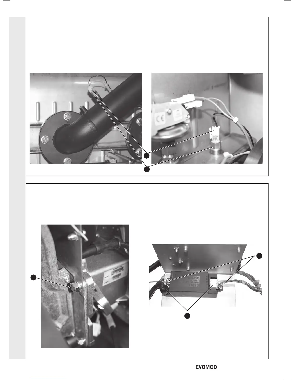
SPARK GENERATOR
6
5
57
FLOW AND RETURN THERMISTOR REPLACEMENT
1. Refer to Frame 40.
2. Remove the module front cover (refer to Frame 44).
3. Remove the right hand side panel (refer to Frame 15).
4. Isolate the water circuit and drain boiler.
5. Pull off the electrical connection.
6. Unscrew the ow and/or return thermistor.
7. Fit the new thermistor/s.
8. Re-assemble in reverse order.
9. Re-ll the system ensuring all the air in the boiler is vented.
10. Refer to Frame 39 for nal safety checks.
Flow Thermistor Return Thermistor
3
5
6
SERVICING
44
- Installation & Servicing

 Loading...


