73
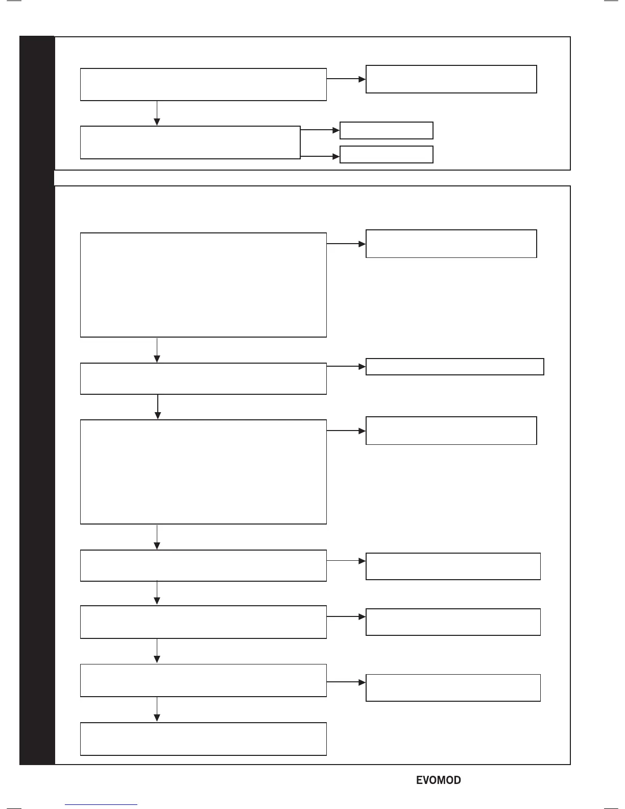
FAN FAULT
Rectify wiring & connections
no
Does the wiring from the Fan to the PCB have secure
connections at both ends and has not deteriorated?
yes
Replace main PCB
Replace Fan
no
yes
Is there 230Vac at the blue and brown
connections to the 3 way connection on the Fan?
74
FLOW THERMISTOR OR RETURN THERMISTOR OR THERMAL FUSE FAULT OR
SAFETY THERMOSTAT OPEN
Fit a new ow thermistor
no
Disconnect the electrical connection to the Flow
Thermistor and check the resistance using a suitable
multimeter connected across the thermistor’s terminal
pins.
At 25°C expect 9,700 - 10,300 Ω
At 60°C expect 2,400 - 2,600 Ω
At 85°C expect 1,000 - 1,100 Ω
Is the thermistor value correct?
yes
Check and replace wiring as necessary
no
Is there continuity between the PCB and the Flow
Thermistor?
Fit a new return thermistor
no
Disconnect the electrical connection to the Return
Thermistor and check the resistance using a suitable
multimeter connected across the thermistor's terminal
pins.
At 25°C expect 9,700 - 10,300 Ω
At 60°C expect 2,400 - 2,600 Ω
At 85°C expect 1,000 - 1,100 Ω
Is the thermistor value correct?
yes
Check and replace wiring as necessary
no
Is there continuity between the PCB and the Return
Thermistor?
yes
Disconnect the electrical connection to the Thermal
Fuse. Is there continuity across the Thermal Fuse?
yes
Replace the Thermal Fuse
Go to Frame 74A
no
no
yes
yes
Disconnect the electrical connection to the safety thermostat.
Is there continuity across the safety thermostat?
Replace the Module PCB
52
- Installation & Servicing

 Loading...


