78
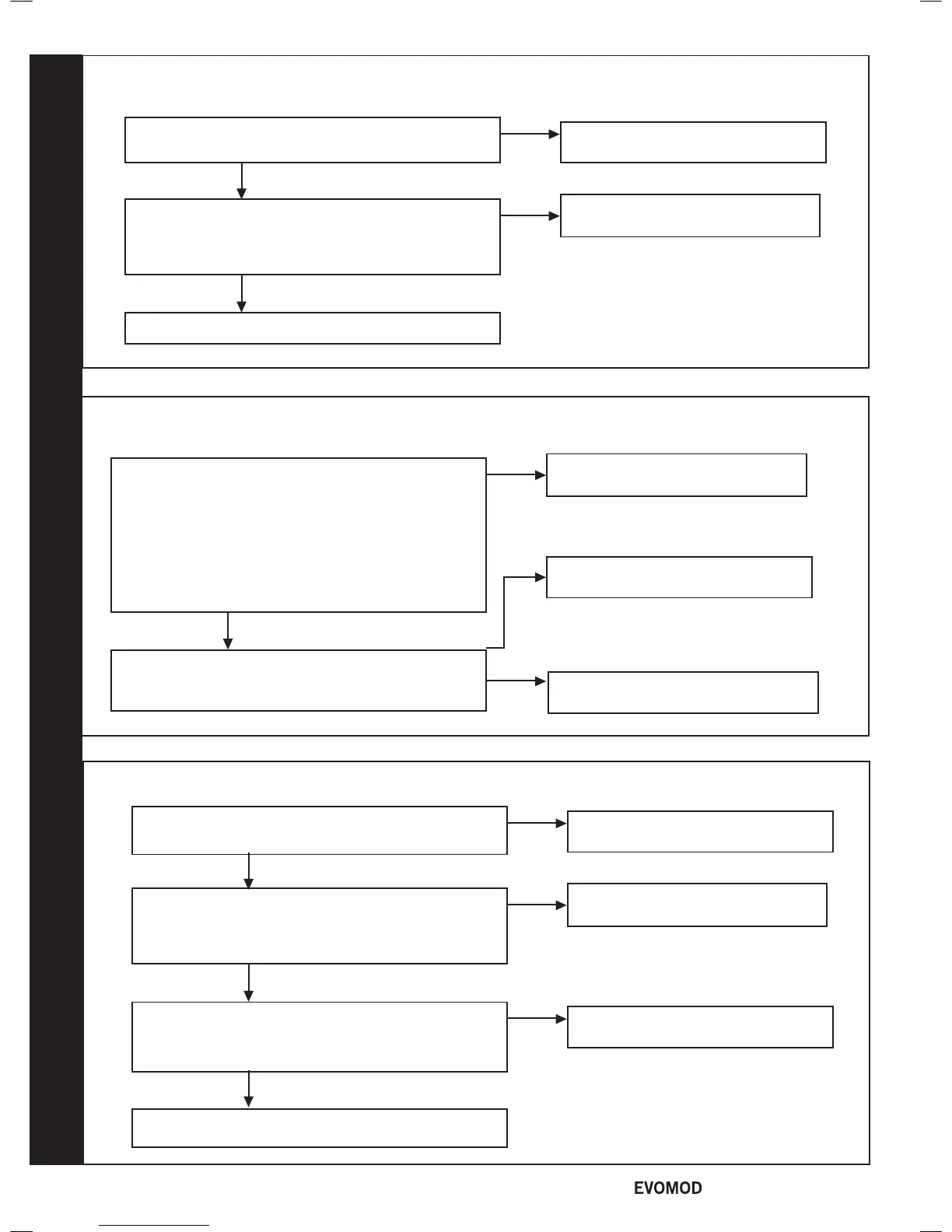
HEADER THERMISTOR
Fit a new Header Thermistor
no
Disconnect the electrical connection to the Header
Thermistor and check the resistance using a suitable
multimeter connected across the thermistor's terminal
pins.
At 25°C expect 9,700 - 10,300 Ω
At 60°C expect 2,400 - 2,600 Ω
At 85°C expect 1,000 - 1,100 Ω
Is the thermistor value correct?
yes
Check and replace wiring as
necessary
no
Is there continuity between the PCB and the Header
Thermistor?
Replace the Master PCB
yes
79
CUI WIRING (USER INTERFACE)
Replace the wiring from the Master
PCB to the User Interface PCB
no
Does the Wiring from the Master PCB to the User
Interface PCB have continuity
yes
No further action required
yes
Replace The User Interface PCB. Has the fault
disappeared?
yes
Replace the Master PCB
No further action required
yes
Turn the power to the boiler off and then on. Has the
fault disappeared?
no
77
MODULE NOT CONNECTED
Replace the eBus wiring from the
Master PCB to the Module PCB
no
Does the eBus wiring from the Master PCB to the
Module PCB have continuity?
yes
Replace the Module PCB
Replace the 230V wiring from the
Master PCB to the Module PCB
no
Is there 230V to the unconnected module?
yes
54
- Installation & Servicing

 Loading...


