14
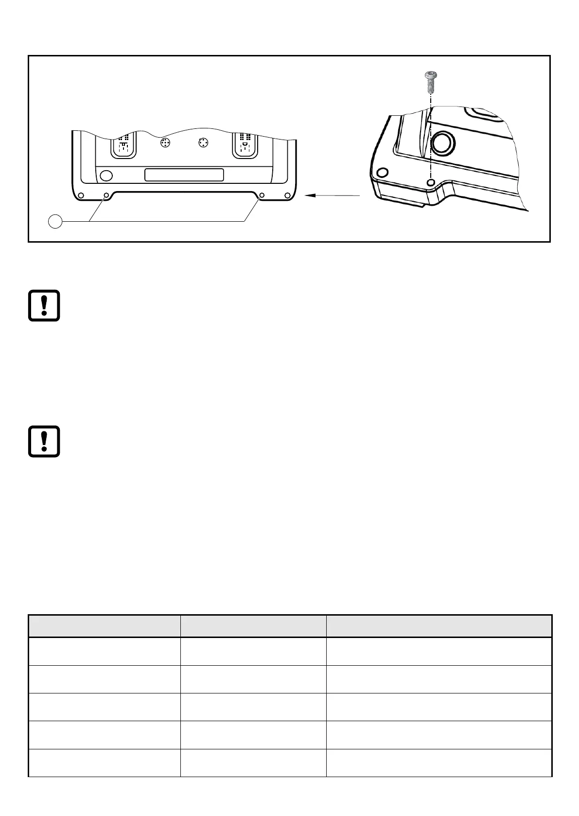
6.3 Shield connection
EPS Source
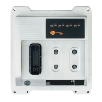
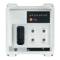
Product Scale Drawing
Frame Size: 80 mm x 49,5 mm
Original Scale Drawing (MTD)
P_MZ_e100_0093
Scale: 1:2
18
47
206
219
250
271
6,4 M12x1
LEDs
1
2
1
1: Holes for shield connection
To ensure the protection of the device against electrical interference and to
ensure the safe function of the device, the housing has to be connected to
the body / GND of the supply using the shortest possible route�
Otherwise the safety function is not ensured!
► Connect the device to the ground of the vehicle using the M4 self-tapping
screw (included)�
Only use the supplied screw for the shield connection on the device to
avoid corrosion�Tightening torque: 3�0
±0,2
Nm
To avoid contact corrosion on the shield connection of the device, do not
use any stainless steel, copper or nickel-plated materials for the bolting
element!
6.4 Fuses
► The individual electric circuits must be protected in order to protect the whole
system� Automotive spade-type fuses are recommended�
Connection Nominal value fuse Required triggering characteristics
VBB
15
2 A T
fuse
≤ 120 s at max. 6.25 A
VBB
30
2 A T
fuse
≤ 120 s at max. 6.25 A
VBB
0
15 A -
VBB
1
≤ 15 A -
VBB
2
≤ 15 A -