15
UK
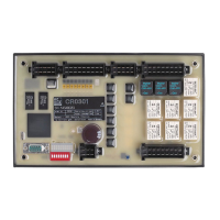
Connection Nominal value fuse Required triggering characteristics
VBB
3
≤ 15 A -
VBB
4
(only with
CR721S)
≤ 15 A -
VBB
5
(only with
CR721S)
≤ 15 A -
Inputs / input groups 2 A T
fuse
≤ 120 s at max. 6.25 A
All supply lines of the inputs can be protected within the input groups�
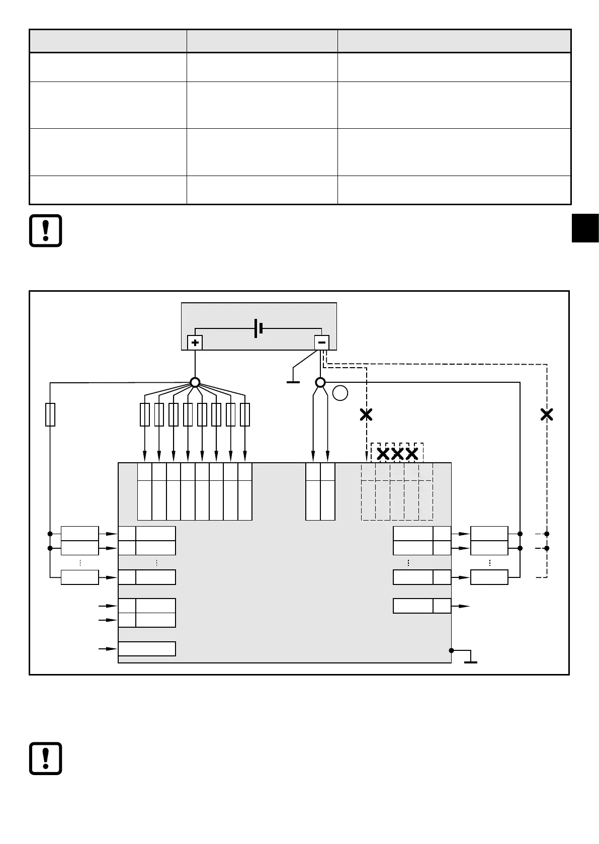
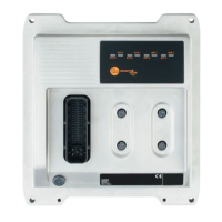
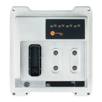
6.5 Laying of the supply and signal cables
supply
output
nn
output
nn
output
nn
controller
VBB
30
nn
VBB
15
nn
VBB
0
nn
VBB
1
nn
VBB
2
nn
VBB
3
nn
VBB
4
nn
VBB
5
nn
GND
SYS
nn
GND
1...4
GND
SYS
GND
RES
GND
ANA
GND
OVA
GND
1...4
nn
input
nn
input
nn
GND
ANA
nn
nn
input
nn
sensor
sensor
sensor
load
load
load
GND
OVA
Shield
nn
nn
nn
nn
nn
nn
GND
RES
RESET-COM
Connection of the supply and signal cables (X = not permitted), example CR721S
1: GND star point
Bridging of connections in the connectors is not permitted�
RESET-COM is a service input (see programming manual)�