8 Image Vault
®
PRO Command
3 Connecting System Components
Pick a level surface to place the Digital Video Recorder (DVR). The system should have adequate ventilation and should be clear of
moisture and dirt. The following sections detail setup of speci c items.
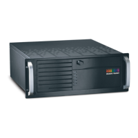
3.1 4 Camera/30 FPS Model: Video & Audio Capture, Monitor Output
Video In: Connect up to 4 NTSC video cameras to the BNC connectors on the main breakout cable. The breakout cable is connected to
the DB15 port on the rear of the DVR.
Audio In: Connect one line level audio microphone source to the RCA connector on the breakout cable.
Video Out: Connect the NTSC Public View Monitor (PVM) to the RCA connector on the rear of the DVR. The PVM output cycles between
camera inputs.
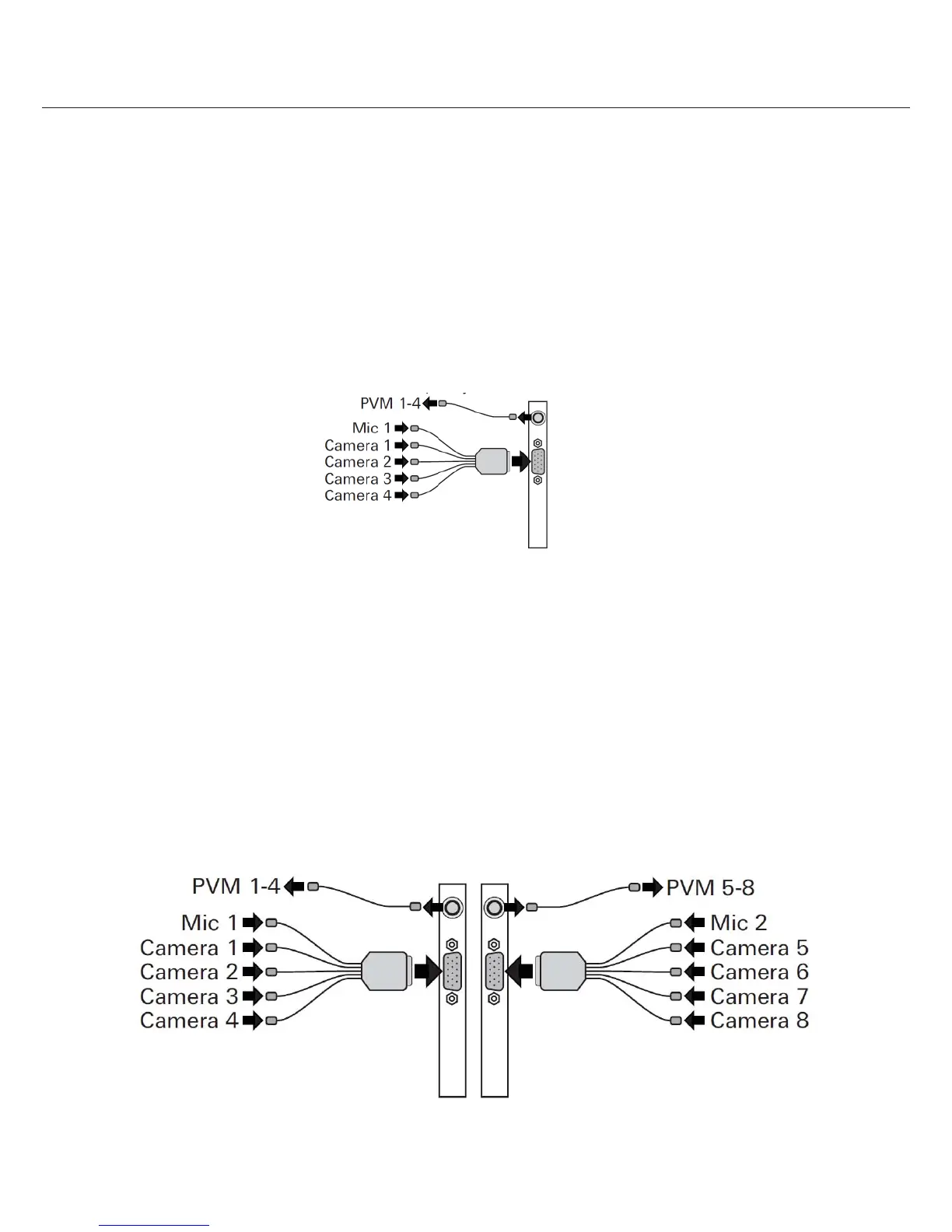
3.2 8 Camera/60 FPS Model: Video & Audio Capture, Monitor Output
Video In: Connect up to 8 NTSC video cameras to the BNC connectors on the main breakout cables. The breakout cables are
connected to the DB15 port on the rear of the DVR. Cameras 1 to 4 connect to the left and Cameras 5 to 8 connect to the right.
Audio In: Connect one line level audio microphone source to the RCA connector on each breakout cable. The microphone connected
to the left is associated with cameras 1 to 4; the microphone connected to the right side is associated with cameras 5 to 8.
Video Out: Connect an NTSC Public View Monitor (PVM) to the RCA connector to the left to see a cycling output from cameras 1 to 4.
Connect an NTSC Public View Monitor (PVM) to the RCA connector to the right to see a cycling output from cameras 5 to 8.