9 Image Vault
®
PRO Command
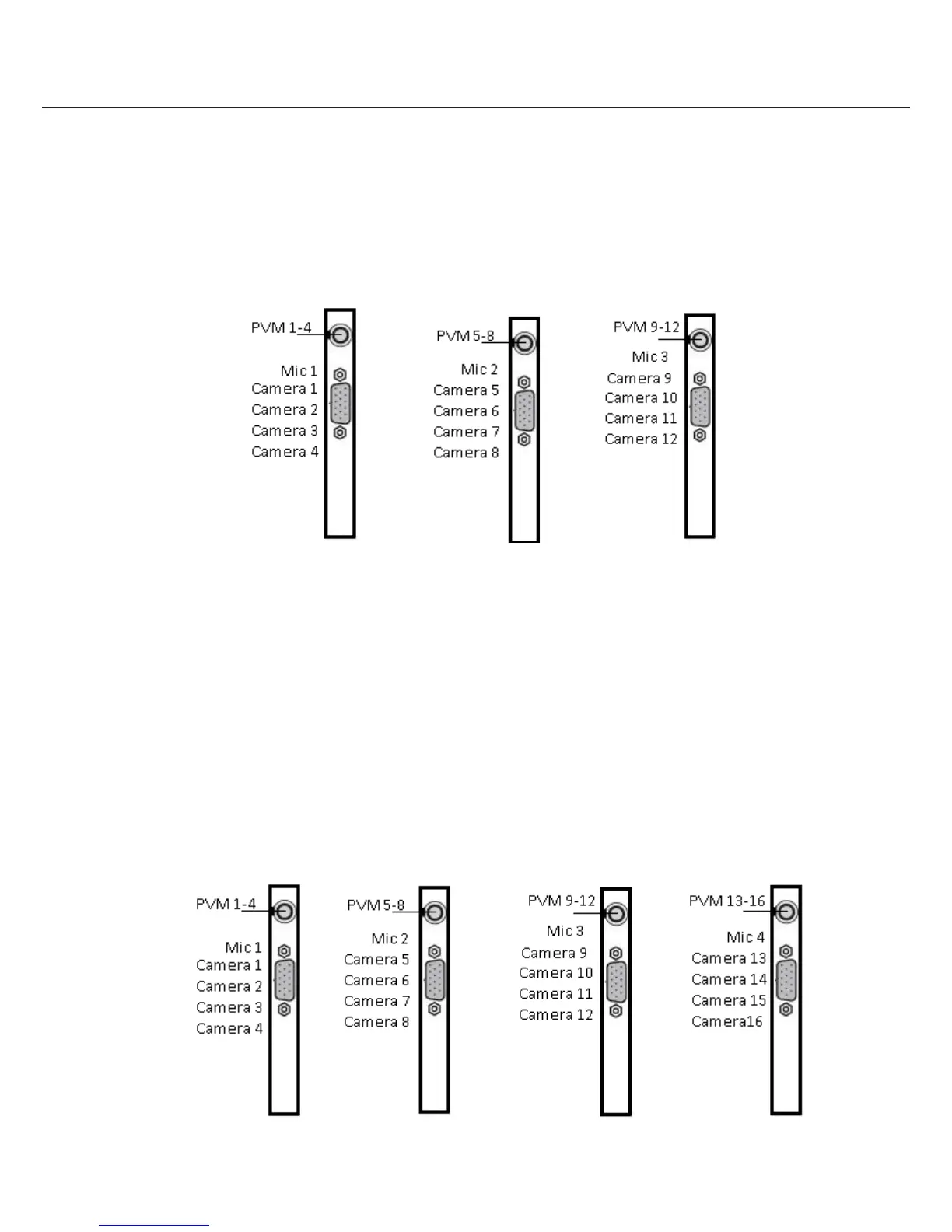
3.3 12 Camera/90 FPS Model: Video & Audio Capture, Monitor Output
Video In: Connect up to 12 NTSC video cameras to the BNC connectors on the main breakout cables (Example 3.3). The
breakout cables are connected to the DB15 port on the rear of the DVR. Cameras are connect as listed below.
Audio In: Connect one line level audio microphone source to the RCA connector on each card. Microphone 1 is associated
with cameras 1 to 4; Microphone 2 is associated with cameras 5 to 8; Microphone 3 is associated with cameras 9 to 12.
Video Out: Connect an NTSC Public View Monitor (PVM) to the RCA connector on the 1st card to see a cycling output from
cameras 1 to 4. Connect an NTSC Public View Monitor (PVM) to the RCA connector to the 2nd card to see a cycling output from
cameras 5 to 8. Connect an NTSC Public View Monitor (PVM) to the RCA connector to the 3rd card to see a cycling output from
cameras 9 to12.
3.4 16 Camera/120 FPS Model: Video & Audio Capture, Monitor Output
Video In: Connect up to 16 NTSC video cameras to the BNC connectors on the main breakout cables (Example 3.4). The
breakout cables are connected to the DB15 port on the rear of the DVR. Cameras are connect as listed below.
Audio In: Connect one line level audio microphone source to the RCA connector on each card. Microphone 1 is associated
with cameras 1 to 4; Microphone 2 is associated with cameras 5 to 8; Microphone 3 is associated with cameras 9 to 12: Micro-
phone is associated with cameras 13 to 16.
Video Out: Connect an NTSC Public View Monitor (PVM) to the RCA connector on the 1st card to see a cycling output from
cameras 1 to 4. Connect an NTSC Public View Monitor (PVM) to the RCA connector to the 2nd card to see a cycling output from
cameras 5 to 8. Connect an NTSC Public View Monitor (PVM) to the RCA connector to the 3rd card to see a cycling output from
cameras 9 to12. Connect an NTSC Public View Monitor (PVM) to the RCA connector to the 4th card to see a cycling output from
cameras 13 to 16.