© 2018 imc Test & Measurement GmbH
imc C-SERIES - Manual, Version 4 R 3 - 2018-10-19
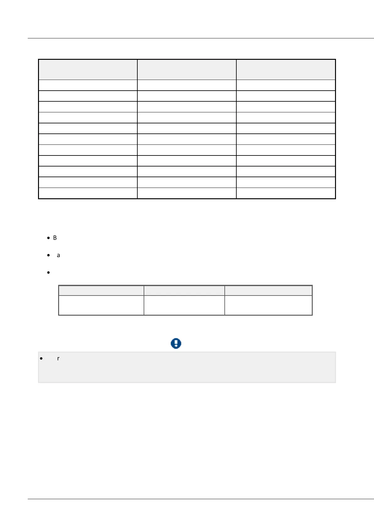
103CS-5008-FD, CL-5016-FD
Possible initial unbalance
bridge balancing
(VB = 5 V) [mV/V]
bridge balancing
(VB = 10 V) [mV/V]
5.7.1.5 Balancing and shunt calibration
The amplifier offers a variety of possibilities to trigger bridge balancing:
·
Balancing / shunt calibration upon activation (cold start) of the unit. If this option is selected, all the
bridge channels are balanced as soon as the device is turned on.
·
Balancing / shunt calibration via graphical user interface of device software (channel balance
respectively amplifier balance)
·
In shunt calibration, the bridge is unbalanced by means of a 59.8 kΩ or 174.66 kΩ shunt. The results
are:
The procedures for balancing bridge channels also apply analogously to the voltage measurement mode
with zero-balancing.
·
We recommend setting channels which are not connected for voltage measurement at the highest
input range. Otherwise, if unconnected channels are in quarter- or half-bridge mode, interference
may occur in a shunt calibration!