EasyManuals Logo

IMC C SERIES User Manual

IMC C SERIES
185 pages
To Next Page IconTo Next Page
To Previous Page IconTo Previous Page
Page #170 background imageLoading...
Page #170 background image
© 2018 imc Test & Measurement GmbH
imc C-SERIES - Manual, Version 4 R 3 - 2018-10-19
170 Pin configuration
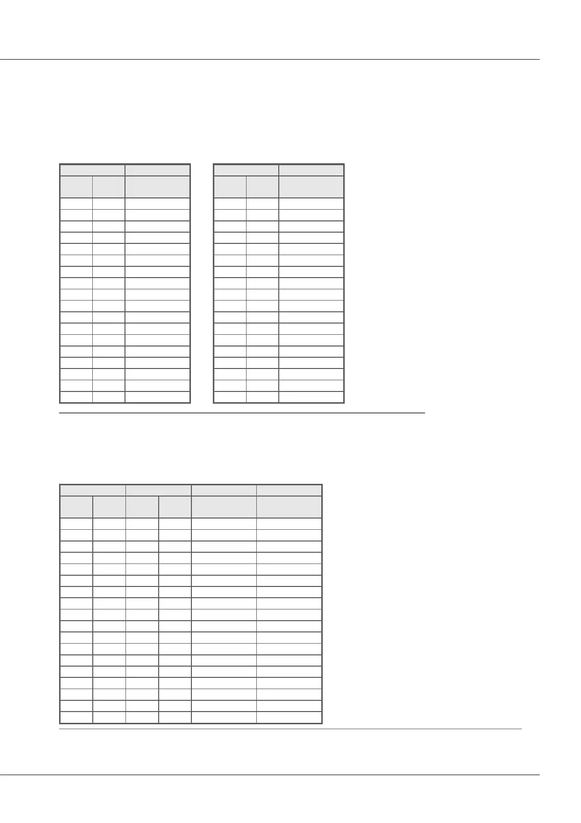
7.3 DSUB-15 pin configuration
In general: DSUB pin 1 is internally reserved.
7.3.1 Universal connector
Plastic
ACC/DSUB-
UNI2
DSUB
Pin
Terminal
UNIVERSAL
9
1
+VB1
2
2
+IN1
10
3
-IN1
3
4
-VB1
11
5
I1_1/4B1 *
4
6
-SENSE1
12
7
+VB2
5
8
+IN2
13
9
-IN2
6
10
-VB2
14
11
I2_1/4B2 *
7
12
-SENSE2
15
14
GND
8
17
+5V
13
18
15
CHASSIS
16
CHASSIS
Metal connector
ACC/DSUBM-
UNI2
DSUB
Pin
Terminal
UNIVERSAL
9
1
+VB1
3
2
-VB1
2
3
+IN1
10
4
-IN1
11
5
I1_1/4B1*
4
6
-SENSE1
5
7
+IN2
13
8
-IN2
14
9
I2_1/4B2*
7
10
-SENSE2
12
11
+VB2
6
12
-VB2
15
15
(GND)
8
18
(+5V)
13
14
16
CHASSIS
17
CHASSIS
* if special version of the device is equipped with ±15 V option, then this pin = -15 V
7.3.2 Standard connector
Plastic
Metal connector
ACC/DSUB-
ACC/DSUBM-
B2
U4
DSUB
Pin
Terminal
DSUB
Pin
Terminal
BRIDGE
VOLTAGE
9
1
9
1
+VB1
(RES.)
2
2
2
2
+IN1
+IN1
10
3
10
3
-IN1
-IN1
3
4
3
4
-VB1
(+SUPPLY)
11
5
11
5
[+SENSE1_1/4B1]
+IN2
4
6
4
6
-SENSE1
-IN2
12
7
12
7
+VB2
(-SUPPLY)
5
8
5
8
+IN2
+IN3
13
9
13
9
-IN2
-IN3
6
10
6
10
-VB2
(GND) *
14
11
14
11
[+SENSE2_1/4B2]
+IN4
7
12
7
12
-SENSE2
-IN4
15
14
15
15
GND
(GND)
8
17
8
18
+5V
(+5V)
13
13
18
14
15
16
CHASSIS
CHASSIS
16
17
CHASSIS
CHASSIS
[ ] : 1/4 Bridge with Cx-70xx and Cx-50xx
* if special version with ±15 V option, then this pin 6 is the reference

Table of Contents

Questions and Answers:

Question and Answer IconNeed help?

Do you have a question about the IMC C SERIES and is the answer not in the manual?

IMC C SERIES Specifications

General IconGeneral
BrandIMC
ModelC SERIES
CategoryMeasuring Instruments
LanguageEnglish

Related product manuals