© 2018 imc Test & Measurement GmbH
imc C-SERIES - Manual, Version 4 R 3 - 2018-10-19
51Measurement types
4.7 Measurement with current-fed sensors (IEPE)
With current-fed sensors (e.g. ICP™-, DELTATRON®-, PIEZOTRON®-, PIEZOBEAM®-sensors), the capacitive
burden on the signal due to the cable capacitance can lead to clipped amplitudes for higher frequencies.
To avoid signal distortion, try to:
1. keep the cable short,
2. use a low-capacitance cable,
3. use a less sensitive sensor.
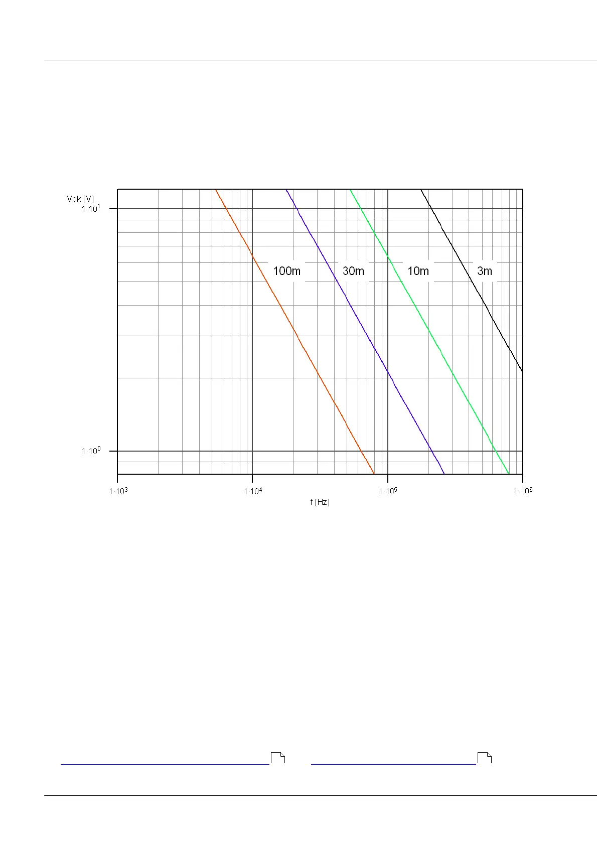
Maximum signal amplitudes as a function of the signal frequency and the cable length, with a 4 mA feed
and a capacitance of 100 pF/m.
4.7.1 Supply current
The exact magnitude of the supply current is irrelevant for the measurement's precision. Values of 2 mA
tend to be adequate. Only in the case of very high bandwidth and amplitude signals in conjunction with
very long cables, supply currents may be a concern, as considerable currents are need to dynamically
charge the capacitive load of the cable.
cable capacity (typ. coax-cable):
max. signal slew rate (full-power):
dU/dt = 5 V * 2 * PI * 25 kHz
L
max
= 4 mA / (100 pF/m * 5 V * 2 * PI * 25 kHz) = 50 m
Up to a max. cable length of 50 m, no limitations are to be expected as long as the conditions above are
fulfilled.
Find here the description of the ICP-connector and here technical specs: ACC/DSUB-ICP.
52 158