© 2018 imc Test & Measurement GmbH
imc C-SERIES - Manual, Version 4 R 3 - 2018-10-19
109CS-5008-FD, CL-5016-FD
5.8 CS-7008-FD, CL-7016-FD
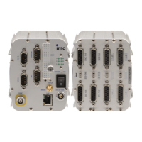
CS-7008-FD and CL-7016-FD are 8- and 16-channel universal measurement devices, respectively, with
sampling rates of up to 100 kHz per channel. They are especially well suited to frequently changing
measurement tasks. Practically every sensor- or signal type can be connected directly to any of the
measurement amplifier’s all-purpose channels. The input channels are differential and equipped with
per-channel signal conditioning including filters.
To supply external sensors or bridges the module is equipped with a sensor supply with an adjustable
supply. The analog channels supportsTEDS (Transducer Electronic Data Sheets (IEEE 1451)
The measurement inputs whose terminals are DSUB plugs (are for voltage, current, bridge, PT100 and
thermocouple measurements. In addition the use of an IEPE/ICP-expansion plug is possible. They are
non-isolated differential amplifiers. They share a common voltage supply for sensors and measurement
bridges.
Technical details: CS-7008-FD, CL-7016-FD analog inputs
5.8.1 Voltage measurement
·
Voltage: ±50 V to ±5 mV; DSUB-plug: ACC/DSUBM-UNI2
Within the voltage ranges ±50 V and ±20 V, a voltage divider is in effect; the resulting input impedance is
1 MΩ.
By contrast, in the voltage ranges ±10 V and ±5 mV, the input impedance is 20 MΩ. For the deactivated
device, the value is approx. 1 MΩ.
In the input ranges <20 V, the common mode voltage
1
must lie within the ±10 V range. The range is
reduced by half of the input voltage. The input configuration is differential and DC-coupled.
The common mode voltage is the arithmetic mean of the voltages at the inputs +IN and -IN, referenced to the
device ground. For instance, if the potential to ground is +10 V at +IN and +8 V at -IN, the common mode
voltage is +9 V.
With the predecessor C-70xx: If the input signal level violates the negative measurement range
boundary, then the measurement readings are not limited to the maximum measurement range
boundary value. Instead, the measurement readings are displayed within the range corresponding to
the measurement range setting. This effect occurs in the measurement ranges 50/60 V, 10 V, 2/2.5 V
and 0.5 V.
124
28
147

 Loading...