© 2018 imc Test & Measurement GmbH
imc C-SERIES - Manual, Version 4 R 3 - 2018-10-19
107CS-5008-FD, CL-5016-FD
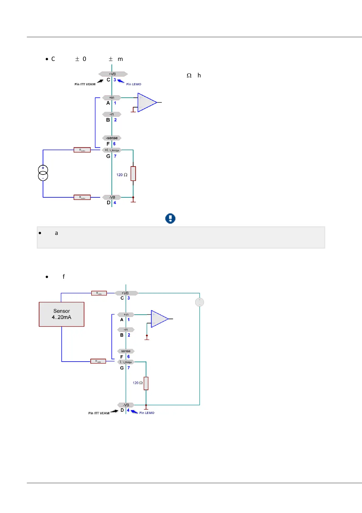
5.7.3.2 Ground-referenced current measurement
·
Current:
±
50 mA to
±
2 mA
In this circuit, the current to be measured flows through
the 120
W
shunt in the amplifier. Note that here, the
terminal -VB(D) is simultaneously the device's ground.
Thus, the measurement carried out is single-end or ground
referenced. The potential of the current source itself may
be brought into line with that of the units ground. In that
case, be sure that the device unit itself is grounded.
In the settings interface, set the measurement mode to
Current.
Note that the jumper between +IN(A) and +I; ¼Bridge(G)
should be connected right inside the connector.
·
For an (optional) sensor supply with ±15 V ground referenced current measurement is not possible.
The pin I;¼Bridge is used as –15 V pin.
5.7.3.3 2-wire for sensors with a current signal and variable supply
·
E.g. for pressure transducers 4 mA to 20 mA
Transducers which translate the physical
measurement quantity into their own
current consumption and which allow
variable supply voltages can be configured
in a two-wire circuit. In this case, the device
has its own power supply and measures the
current signal.
In the settings dialog on the index card
Universal amplifiers/ General, a supply
voltage is set for the sensors, usually 24 V.
The channels must be configured for
Current measurement.
The sensor is supplied with power via
Terminals +VB(C) and +I; ¼
Bridge
(G).
The signal is measured by the amplifier
between +in(A) and I; ¼
Bridge
(D). For this
reason, a wire jumper must be positioned
between Pins +in(A) and I; ¼
Bridge
(G) inside
the connector pod.

 Loading...