© 2018 imc Test & Measurement GmbH
imc C-SERIES - Manual, Version 4 R 3 - 2018-10-19
175DSUB-9 pin configuration
* Pin configuration at measurement device. At the GPS-mouse Rx and Tx are interchanged.
7.5.3 CAN FD
unused as per standard*
(supply I < 1 A)
unused as per standard*
(supply I < 1 A)
Find here the technical data and the cabling of the CAN-Bus interface.
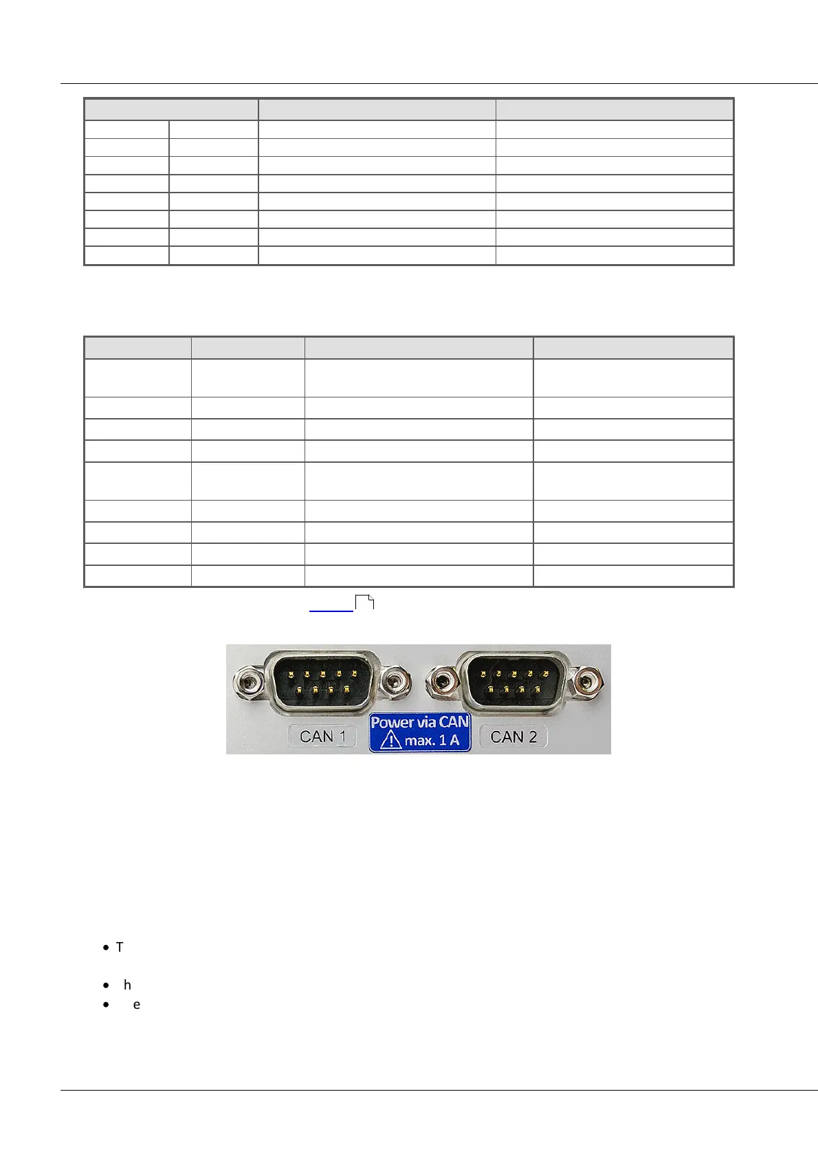
* The CAN FD Interface can be equipped ex-factory with the option "Power via CAN".
The DSUB-9 sockets are labled.
CAN FD Interface with Power via CAN
The special option Power via CAN includes the internal connection of the unbuffered supply voltage of
the device to the first two nodes "CAN1" and "CAN2" of the CAN interface of a device. This makes it
possible to supply connected CANSAS modules (or CAN-based sensors) via the CAN cable. A cable with
sufficient cross-section is required. The load current is a maximum of 1 A per node and is limited by a
current limiter, which does not provide safe short-circuit protection.
Direction of electric current and fuse
·
The direction of current flow is unidirectional, protected by diodes: the device supplies CAN bus
participants. Current flow into the device is blocked.
·
The diodes also decouple the supply lines of the two CAN nodes from each other.
·
Overload protection is provided by an over current protection in the form of inert PTC components
("PolySwitch"). These will be reset in case and the operational again.
74