© 2018 imc Test & Measurement GmbH
imc C-SERIES - Manual, Version 4 R 3 - 2018-10-19
30 Properties of the imc C-SERIES
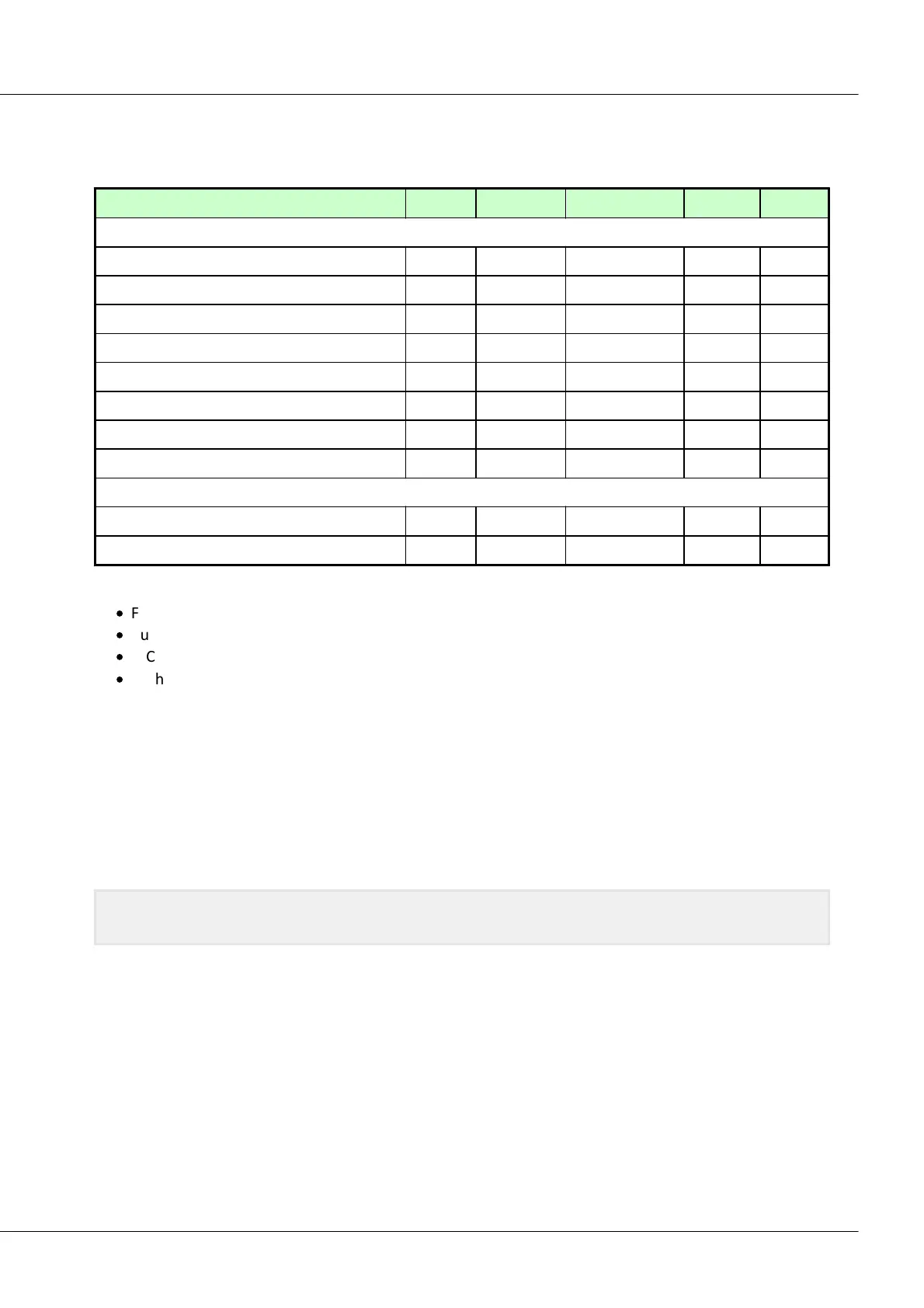
4.6.1.1 Thermocouples as per DIN and IEC
The following standards apply for the thermocouples, in terms of their thermoelectric voltage and
tolerances:
Iron-constantan (Fe-CuNi)
Copper-constantan (Cu-CuNi)
Nickel-chromium-Nickel (NiCr-Ni)
Nickel-chromium-constantan (NiCr-CuNi)
Nicrosil-Nisil (NiCrSi-NiSi)
Platinum-Rhodium-platinum (Pt10Rh-Pt)
Platinum-Rhodium-platinum (Pt13Rh-Pt)
Platinum-Rhodium-platinum (Pt30Rh-Pt6Rh)
Iron-constantan (Fe-CuNi)
Copper-constantan (Cu-CuNi)
If the thermo-wires have no identifying markings, the following distinguishing characteristics can help:
·
Fe-CuNi: Plus-pole is magnetic
·
Cu-CuNi: Plus-pole is copper-colored
·
NiCr-Ni: Minus-pole is magnetic
·
PtRh-Pt: Minus-pole is softer
The color-coding of compensating leads is stipulated by DIN 43713. For components conforming to IEC
584: The plus-pole is the same color as the shell; the minus-pole is white.
4.6.1.2 Pt100 (RTD) - measurement
Aside from thermocouples, RTD (Pt100) units can be directly connected in 4-wire-configuration (Kelvin
connection). An additional reference current source feeds a chain of up to 4 sensors in series.
With the imc Thermo connector, the connection terminals are already wired in such a way that this
reference current loop is closed "automatically".
If fewer than 4 Pt100 units are connected, the current-loop must be completed by a wire jumper from
the "last" RTD to -I4.
If you dispense with the "support terminals" (±I1 to ±I4) provided in the imc Thermo connector for 4-wire
connection, a standard terminal connector or any DSUB-15 connector can be used. The "current loop"
must then be formed between +I1 (DSUB Pin 9) and -I4 (DSUB Pin 6).