© 2018 imc Test & Measurement GmbH
imc C-SERIES - Manual, Version 4 R 3 - 2018-10-19
34 Properties of the imc C-SERIES
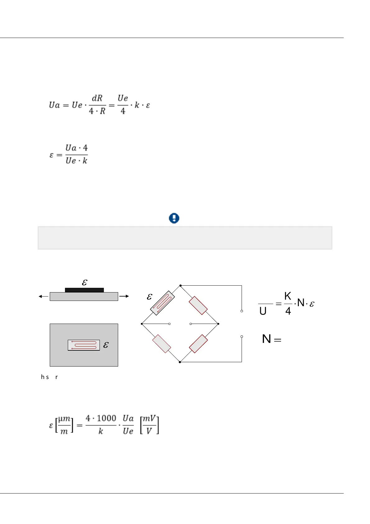
The changes in resistance caused by the strain are very small. For this reason, a bridge circuit is used to
translate these changes into voltage changes. Depending on the circuit, from one to four WSGs can be
employed as bridge resistors.
Assuming that all bridge resistors have the same value, we have:
Ua: measurement voltage
Ue: excitation voltage
For concrete measurement tasks, the arrangement of the WSGs on the test object is important, as well
as the circuitry of the bridge. On the card "Bridge circuit", you can select from among typical
arrangements. A graphic shows the position on the test object and the bridge circuitry. Notes on the
selected arrangement are displayed in the text box beneath.
For easier operation, input ranges that are unsuitable for metrological purposes are hidden in the
operating software.
4.6.2.2.1 Quarter bridge for 120 Ohm WSG
R
2
R
3
R
4
U
IN
U
B
1
1
1
This strain gauge arrangement uses an active WSG which is positioned on the test object in a uniaxial
stress field. This WSG is joined by three passive resistors within the module to form a full bridge. The
strain gauge can have a resistance value of 120 Ω.
This arrangement does not come with temperature compensation. The strain is computed as:
k: gauge factor