© 2018 imc Test & Measurement GmbH
imc C-SERIES - Manual, Version 4 R 3 - 2018-10-19
62 Device description
5.1.1 Digital In- and Outputs, Inputs for Incremental encoders
There are 8 binary inputs, 8 binary outputs and 4 incremental encoder inputs.
5.1.1.1 Digital Inputs
The DI potion possesses 8 digital inputs which can take samples at rates of up to 10 kHz. Every group of
four inputs has a common ground reference and are not mutually isolated. However, this input group is
isolated from the second input group, the power supply and CAN-Bus, but not mutually.
The technical specification of the digital inputs .
The pin configuration of the ACC/DSUB(M)-DI4-8 .
Open inputs are set to have LOW voltage by means of pull-down resistors
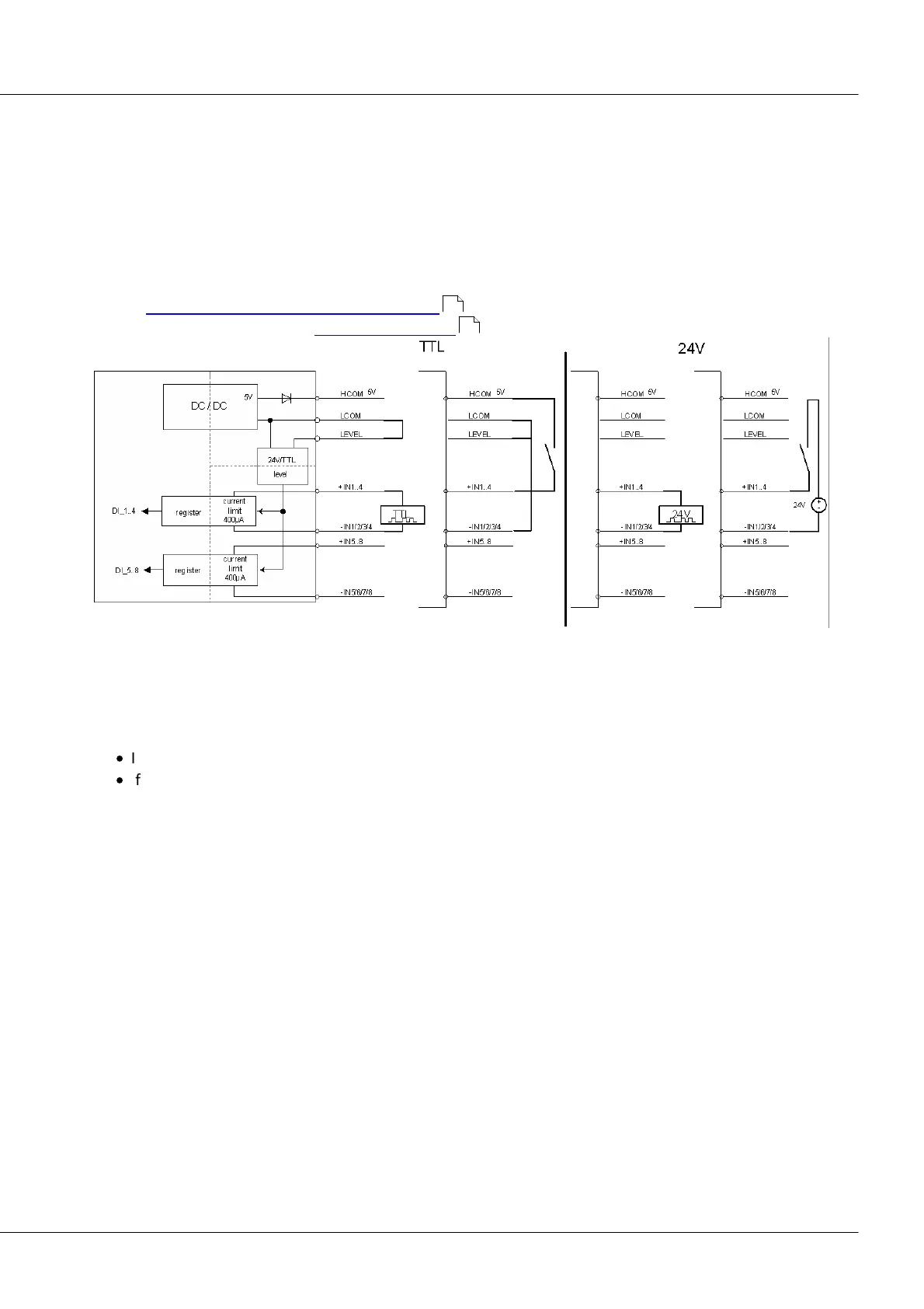
5.1.1.1.1 Input voltage
The input voltage range for a group of eight digital inputs can be set for either 5 V (TTL-range) or 24 V.
The switching is accomplished by means of a jumper at the ACC/DSUB-DI4-8 connector:
·
If LEVEL and LCOM are jumpered, all 8 bits work with 5 V and a threshold of 1.7 V to 1.8 V.
·
If LEVEL is not bridged with LCOM, 24 V and a threshold of 6.95 V to 7.05 V are valid.
Thus, an unconnected connector is set by default for 24 V. This prevents 24 V from being applied to the
voltage input range of 5 V.
152
170

 Loading...