© 2018 imc Test & Measurement GmbH
imc C-SERIES - Manual, Version 4 R 3 - 2018-10-19
76 Device description
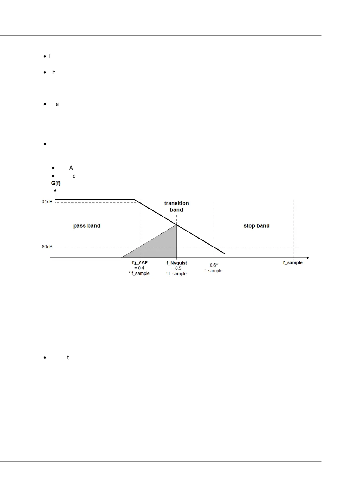
The automatic selection of the cutoff frequency in the setting “AAF” is based on the following criteria:
·
In the pass band, a maximum (AC-) gain uncertainty of 0.06% = -0.005 dB is permitted. The pass
band is defined by the cutoff frequency at which this value is exceeded.
·
The stop band is characterized by attenuation of at least –80 dB. This damping is considered
sufficient for 16-bit systems as well, since discrete disturbance frequencies can never reach 100%
amplitude: the useful input range is mostly filled by the useful signal. Otherwise, a larger range
would have to be selected anyway in order to avoid overranging.
·
The transition band is typically situated symmetrically around the Nyquist-frequency. This ensures
that the aliasing components reflected from the stop band back into the pass band are adequately
suppressed, by at least –80 dB. Remnant components from the frequency range between Nyquist-
frequency and stop band limit only reflect back into the range beyond the pass band (pass band to
Nyquist), whose signal content is defined as not relevant.
·
The criteria stated are fulfilled with the Cauer-filters by the following configuration rule:
Filter-setting “Filter-type”: AAF:
·
fg_AAF (-0.1 dB) = 0.4 * f_sample
·
Characteristics: Cauer; Filter-order: 8th order
Filter-setting “Filter-type: Low-pass”:
A low-pass frequency can be set manually, which satisfies the application’s requirements. In
particular, a cutoff frequency significantly below the Nyquist frequency can be set which guarantees
eliminating aliasing in any case, though consequently “sacrificing” the corresponding bandwidth
reserves.
attenuation at Nyquist-freq.: 1/64
attenuation at Nyquist-freq.: 1/244
attenuation at Nyquist-freq.: 1/15630
·
Characteristics: Butterworth, 8th order (48 dB/octave)
In any case, the setting AAF doesn't guarantee aliasing-free measurement: for every particular
application, check what the requirements for the filter are, and make modifications in case of heavily
disturbed signals. Since the sampling and filter frequencies can be set in steps of 1 – 2 – 5, either 1/4 or
1/5 of the sampling rate is always available as a filter setting.
Additional filter settings options are 4th order bandpass and 4th order high-pass.