27
25
INSTALLER
USER
MAINTENANCE TECHNICIAN
TECHNICAL DATA
1.16 CONFIGURATION TYPE B, OPEN CHAMBER AND
FAN ASSISTED FOR INDOORS.
e appliance can be installed inside buildings in B
22
mode; in this
eventuality, all technical rules and national and local regulations
in force, must be complied with.
1.17 FLUE EXHAUST TO FLUE/CHIMNEY.
Flue exhaust does not necessarily have to be connected to a branched
type traditional ue for type B appliances with natural draught (CCR).
e ue exhaust, for boiler clots installed in C conguration, can be
connected to a special LAS type multiple ue.
For B22 congurations, exhaust is only allowed into individual chim-
ney or directly into the external atmosphere via a relevant terminal,
unless otherwise provided by local regulations.
Multiple and combined ues must be specially designed according to
the calculation method and requirements of the standards in force,
by professionally qualied technical sta. Chimney or ue sections
for connection of the ue exhaust pipe must comply with requisites
of technical standards in force.
1.18 FLUES, CHIMNEYS AND CHIMNEY CAPS.
e ues, chimneys and chimney caps for the evacuation of com-
bustion products must be in compliance with applicable standards.
Chimneys and roof-installed exhaust terminals must comply with
the outlet height and with the distance from technical volumes
set forth by the technical standards in force.
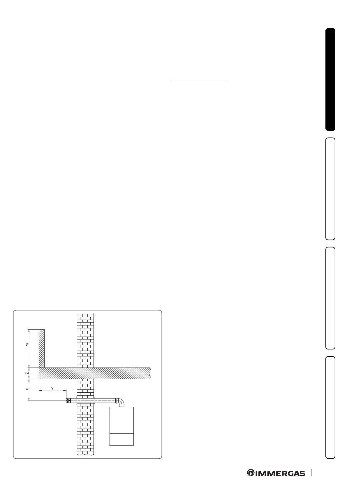
Positioning the wall ue exhaust terminals.
e wall ue exhaust terminals must:
- be installed on external perimeter walls of the building (Fig. 27);
- be positioned according to the minimum distances specied in
current technical standards.
Combustion products exhaust of natural draught or fan assisted
appliances in open-top closed environments.
In spaces closed on all sides with open tops (ventilation pits,
courtyards etc.), direct combustion product exhaust is allowed
for natural draught or fan assisted gas appliances with a heat
input range from 4 to 35kW, provided the conditions as per the
current technical standards are respected.
1.19 SYSTEM FILLING.
Once the boiler is connected, proceed with system lling via the
lling cock (Fig. 34).
Filling is performed at low speed to ensure release of air bubbles
in the water via the boiler and central heating system vents.
e boiler has a built-in automatic venting valve on the circulator.
Check if the cap is loose.
Open the radiator vent valves.
Close radiator vent valves when only water escapes from them.
Close the lling valve when the boiler pressure gauge indicates
approx. 1.2 bar.
N.B.: during these operations turn on the circulation pump at
intervals, by means of the stand-by button located on the control
panel.
Vent the circulation pump by loosening the front cap and keeping
the motor running.
Screw the cap back on aer the operation.
1.20 GAS SYSTEM STARTUP
To start up the system, refer to the technical standards in force.
is divides the systems and, therefore, the commissioning ope-
rations, into three categories: new systems, modied systems,
reactivated systems.
In particular, for new gas systems:
- open windows and doors;
- avoid presence of sparks or naked ames;
- bleed all air from pipelines;
- ensure the internal system is properly sealed according to the
specications set forth by technical regulations in force.
1.21 BOILER START UP IGNITION.
To commission the boiler (the operations listed below must only be
performed by qualied personnel and in the presence of sta only):
- check that the internal system is properly sealed according to
the regulations in force;
- ensure that the type of gas used corresponds to boiler settings;
- check that there is no air in the gas pipe;
- check connection to a 230V-50Hz power mains, correct L-N
polarity and the earthing connection;
- check that there are external factors that may cause the formation
of fuel pockets;
- switch the boiler on and ensure correct ignition;
- make sure that the gas ow rate and relevant pressure values
comply with those given in the manual (Par. 4.1);
- ensure that the safety device is engaged in the event of gas supply
failure and check activation time;
- check activation of the main switch located upstream from the
boiler;
- check that the intake and/or exhaust terminals (if tted) are not
blocked and that they are installed properly.
e boiler must not be started up even if only one of the checks
should be negative.