C
32
C
32
C
32
C
32
15 16
17 18
1
2
3
6
4
7
5
1
2
3
6
8
4
7
5
20
INSTALLER
USER
MAINTENANCE TECHNICIAN
TECHNICAL DATA
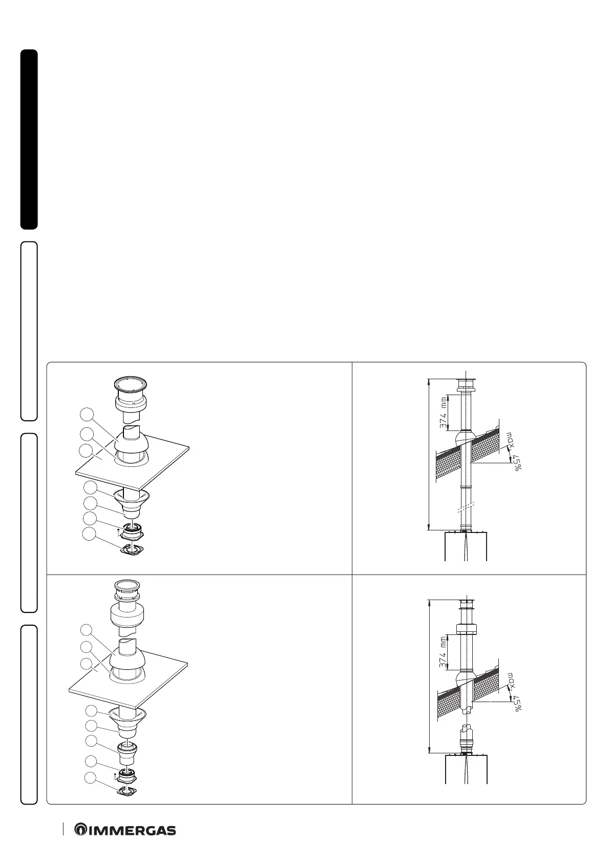
e xing plate kit includes:
N° 1 - Gasket (1)
N° 1 - Female concentric ange (2)
e Kit includes:
N° 1 - Concentric intake-exhaust pipe
Ø 60/100 (3)
N° 1 - Wall sealing plate (4)
N° 1 - Aluminium tile (5)
N° 1 - Fixed half-shell (6)
N° 1 - Mobile half-shell (7)
e kit includes:
N° 1 - Gasket (1)
N° 1 - Female concentric
ange (2)
N° 1 - Adapter
Ø 80/125 (3)
N° 1 - Concentric intake-
exhaust pipe Ø 80/125
(4)
N° 1 - Wall sealing plate (5)
N° 1 - Aluminium tile (6)
N° 1 - Fixed half-shell (7)
N° 1 - Mobile half-shell (8)
• Vertical kit with aluminium tile Ø 80/125. Kit assembly (Fig.
17).
To install the kit Ø 80/125 one must use the anged adapter kit
in order to install the ue system Ø 80/125. Install the anged
adaptor (2) on the central hole of the boiler, positioning gasket
(1) with the circular projections downwards in contact with the
boiler ange, and tighten using the screws contained in the kit.
Installation of the fake aluminium tile: replace the tiles with the
aluminium sheet (4), shaping it to ensure that rainwater runs
o. Position the xed half-shell (5) on the aluminium tile and
insert the intake-exhaust pipe (7). Fit the Ø 80/125 concentric
terminal pipe with the male side (smooth) to the female side
of the adapter (1) (with lip gaskets) up to the end stop; making
sure that the wall sealing plate (3) has been tted, this will ensure
sealing and joining of the elements making up the kit.
• Extensions for vertical kit Ø 80/125 (Fig. 18).
e kit with this conguration can be extended up to a max.
length of 12.2 m including the terminal. If additional components
are assembled, the length equivalent to the maximum allowed
must be subtracted. In this case specic extensions must be
requested.
1.13 SEPARATOR KIT INSTALLATION.
• Type C conguration, sealed chamber and fan assisted.
is kit allows air to come in from outside the building and the
exhaust to exit from the chimney, ue or intubated duct through
divided ue exhaust and air intake pipes. Combustion products
are expelled from pipe (S). Air is taken in through pipe (A) for
combustion. Both ducts can be routed in any direction.
Please note the type of installation C
4
must be done with a nat-
ural draught ue. Moreover, with C
5
conguration, intake and
exhaust pipes cannot be installed on opposing walls.
MAXIMUM LENGTH 4700 mm
MAXIMUM LENGTH 12200 mm